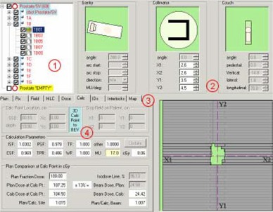
Figure 2.

Screen shot of the RTP‐Filter. The numbered areas correspond to the following descriptions: (1) The prescriptions, beams and segments can be selected by the operator; (2) The position parameters (gantry, collimator, couch, MLC leaves) of each segment can be viewed in the panels in this section; (3) More information about the plan, the selected prescription, field and MLC, the dose, beam IDs, interlocks and intensity maps can be reviewed by selecting the appropriate tabs; (4) Pinnacle plan to LANTIS field comparisons are done when the user performs a dose calculation using the LANTIS data; calculation parameters for flash and effective depths can also be modified in this tab.
