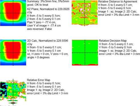
Figure 4.

Sample IMRT QA report from LANTIS. (Note: patient identifiers and physicist's signatures were removed.) The QA method in this report is the 2D calculation using a ray trace through a solid water phantom. All SSDs and depths are calculated from intersections of each ray line with the phantom surface planes. This is done for each point on the grid on the coronal plane through isocenter. The resulting calculated “virtual film” (middle left) is compared against the corresponding Pinnacle calculation (top left) in order to determine the error (bottom left), distance to agreement (top right), and decision (middle right) maps. The calculated data were interpolated onto a common grid.
