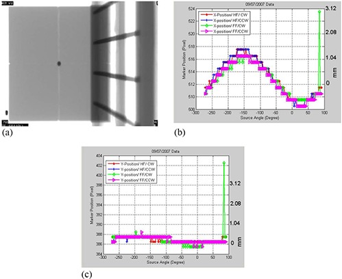
Figure 2.

(a) A cone‐beam radiographic projection where the dark region represents the shadow of the metal marker in the center of the phantom. 2(b) Position shifts of the metal marker in the projections along the x‐axis as a function of view angle, θ, for the CBCT scanning protocols that include half‐fan scan with the gantry rotated clockwise (HF/CW), half‐fan and counter‐clockwise gantry rotation (HF/CCW), and full‐fan scans in which the gantry was rotated clockwise (FF/CW) and counter‐clockwise (FF/CCW), respectively. 2(c) Marker position along the y‐axis (superior‐inferior direction) as a function of gantry angle for the scanning protocols as in Fig. 2(b) for a 21 EX machine with a kV on‐board imager.
