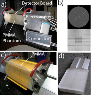
Figure 1.

Delta4 dosimeter in the measurement position (a); CT scan of the device (b) with an axial slice through the center of the measurement region (top) and an oblique reconstruction through the midplane of the main detector board (bottom); the Delta4 phantom with film along the main board and the wings removed (c) with PMMA slab shown half‐inserted, for clarity; assembled calibration phantom (d) with the main detector board inserted.
