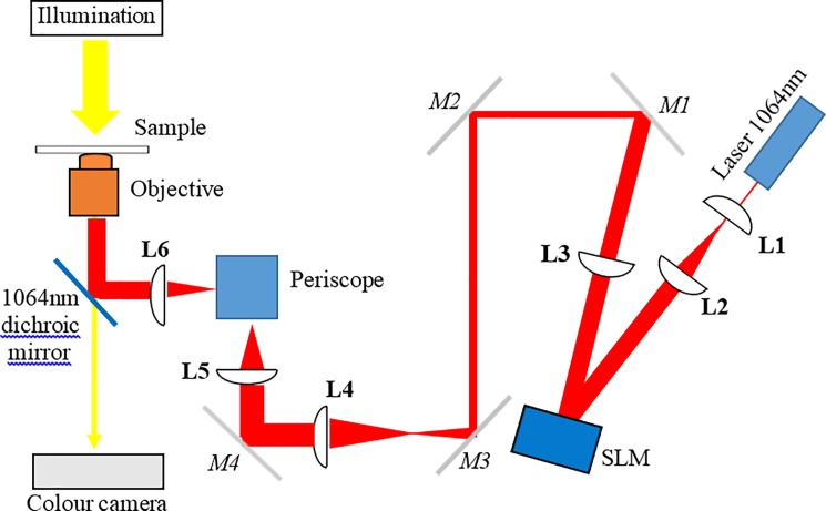
Fig 1. A schematic of the optical trapping system.
A 1064 nm wavelength laser beam was expanded using lenses L1 and L2 to fill the spatial light modulator (SLM) display. The SLM is re-imaged onto mirror 5 (M5), using lenses L3 and L4, and then from M4 onto the back aperture of the microscope objective lens, using lenses L5 and L6. A periscope directs the light into the main body of the microscope and a dichroic mirror reflects the 1064nm light to the sample, transmitting the white light used for imaging. M1-4 are beam steering mirrors.

