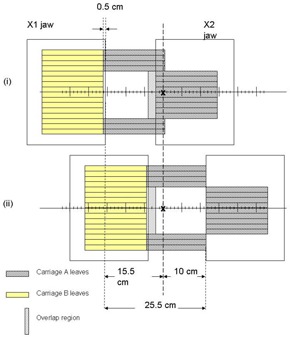
Figure 1(b).

Schematic diagram showing the maximum IMRT treatment field width achievable with dual carriage position delivery. The treatment isocenter is placed such that leaves outside the target region are extended 16 cm across the central axis plane. The first and second carriage positions are depicted as (i) and (ii), with an overlap region as drawn.
