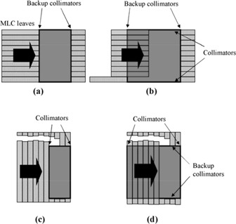
Figure 1.

Field configurations used for testing the dose calculation for segmented fields. In each case, there are five segments. In (a) and (b), modulation is parallel to the direction of MLC leaf motion, whereas in (c) and (d), modulation is perpendicular to the direction of MLC leaf motion. In (c) and (d), pairs of leaves are successively drawn completely across the field so as to narrow its width in the direction of the arrow. In (a) and (c), the segments are defined by both MLC leaves and collimators, whereas in (b) and (d), the segments are defined by MLC leaves only.
