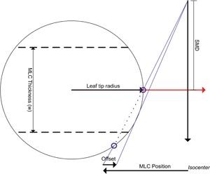
Figure 1.

The geometry of the rounded leaf end and offset used to model the leaf tips of an MLC. The offset of the leaves applied by the accelerator is specified in distances at the isocenter for a range of nominal MLC leaf positions. This offset is applied during the generation in the incident energy fluence. SMD is the source to MLC distance.
