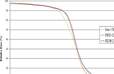
Figure 6.

Profiles for a field defined by MLCs in the direction of leaf travel measured with an ion chamber, PFD diode, and EDR2 film. Note the overresponse under the MLC leaves with film but the agreement between film and diode in the 40% to 100 % dose region.
