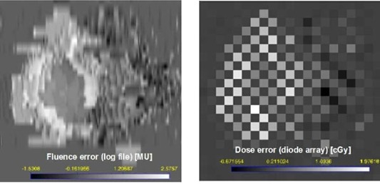
Figure 4.

Absolute dose errors for a single IMRT field: calculated a log file fluence in MU (left) and measured diode array dose in cGy (right) (100 cGy is about equivalent to 100 MU). The bright regions indicate that the delivered dose was larger than the planned dose. Leaves were moving from left to right. The maxMLC overdose covers the left side of the PTV in the BEV. Local deviations from the ideal trajectory result in local fluctuations in dose and are seen as well. . The checkerboard pattern is due to the diode array geometry: diodes are 7 mm apart in a triangular array.
