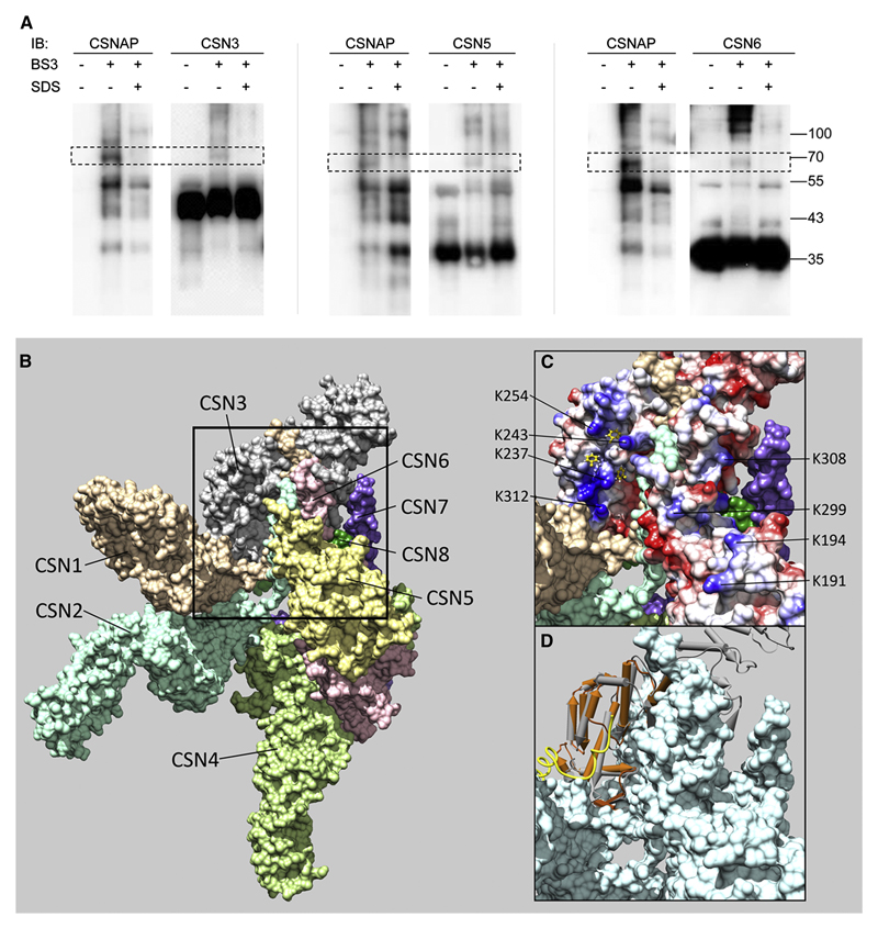
Figure 5. CSNAP interacts with CSN3, CSN5 and CSN6.
(A) FLAG-tagged CSN was purified from HEK293T cells and cross-linked with BS3. As a control for specific CSNAP association, FLAG-CSN was denatured with 1% SDS and boiled for 5 minutes, prior to addition of the cross-linker. After quenching the reaction, the complex was precipitated with acetone, followed by Western blot analysis with antibodies against CSNAP and CSN subunits. The data revealed that CSNAP forms a cross-link with CSN3, CSN5 and CSN6. (B) An overall view of the CSN crystal structure, showing the surfaces of the eight subunits(Lingaraju et al., 2014). The black frame delineates the region where CSN3, CSN5, and CSN6 are found in close proximity. This region enlarged in (C) and (D), includes the C-terminal helices of CSN3 and CSN6, and the loop 284-295 of CSN5, which connects its two C-terminal helices. (C) The electrostatic potential on the surfaces of CSN3, CSN5 and CSN6: blue for positive, red for negative, and white for neutral. The highly positive patch of CSN3 is seen at the top left. Exposed lysine residues which may be involved in cross-linking are indicated: K237, K243, K254, and K312 of CSN3; K191, K194, and K299 of CSN5; and K306 of CSN6. The positive patch includes several hydrophobic pockets, which are preferred anchoring sites of Phe residues, as predicted by ANCHORSmap. Anchored Phe side chains with ΔG<-4 Kcal/mol are shown in yellow. (D) Superposition of the PCI domain of PCID2 (brown) in the complex with DSS1 (Ellisdon et al., 2012), onto the PCI domain of CSN3 (gray). The F/D-rich region of DSS1 (golden coil) binds to the front face of PCID2, which corresponds to the positive patch of CSN3.

