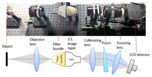
Fig. 2.
Prototype light-guide snapshot spectrometer system setup and schematic layout. The image presented by an objective lens was directly sampled by the input face of the fiber bundle and presented in remapped form at the output end. The distal end of the fiber bundle was 3× reduced in size by the glass image taper and then collimated. A custom glass prism served as light dispersing element. Then, the spectrally separated image was focused and spatially remapped onto a CCD sensor.

