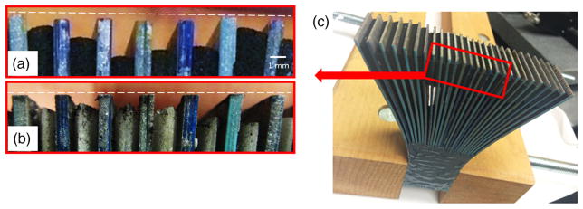
Fig. 8.
Comparison of the output ends of fiber groups in the bundle (a) before and (b) after polishing. The white dotted line represents the position of the image taper. Before polishing the location of the fiber ends does not coincide with the input face of the image taper. After polishing the output faces of all fiber bundle groups now coincide with the white-dotted line, indicating satisfactory surface flatness. (c) Photo of the completed fiber bundle, showing the position of the zoomed area in (a) and (b).

