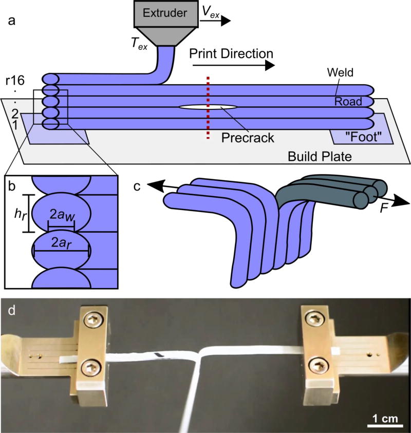
Figure 1.
Schematic of sample preparation and experimental setup. (a) Single road thick samples were printed with the extruder moving from left to right on each pass. The sequential layers are designated r1–r16 from bottom to top. The dotted vertical line illustrates where each printed sample was cut in half to yield two test specimens. (b) Close up of sample edge shows key length scales and symbols for road height, hr, road width, 2ar, and weld width, 2aw. (c) Typical testing configuration of a single specimen where the two free tabs of the specimen are pulled in parallel but opposite directions, driving crack propagation orthogonal to the applied load, F. (d) Photo of test specimen mounted in tensile grips during testing.

