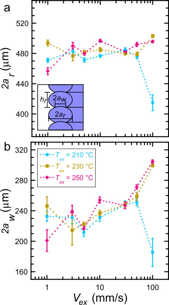
Figure 4.
Weld thickness determination by optical microscopy. (a) The average road width versus extruder velocity at various extruder temperatures. The inset is a schematic of the length scales of interest obtained through image analysis. (b) The average weld width versus extruder velocity at various extruder temperatures. Error bars represent one standard deviation. The values on the x-axis and the legend in (b) apply to both plots.

