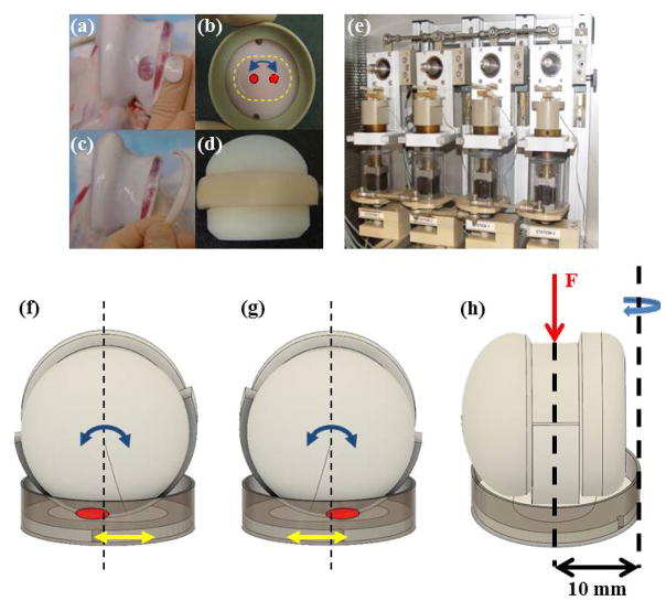
Figure 1.
Image of the disc removed from trochlear groove (a) and secured in semi-confined compression in the polyethylene wafer in a PEEK cup (b). Image of the cartilage strip removed from the trochlear rim (c) and then secured to the polyethylene ball adapted (d). (e) Image of the tribological testing device housed in an incubator where the ball set at the top of the station and rotated at a frequency of 0.5 Hz and a stroke of 30° while the explant rotated at 0.1 Hz and a stroke of 15°. This motion with a contact area of roughly 20 mm2 creates a 5.2 mm curvilinear wear path. (f–g) Diagram of the migrating contact point (red circle) on the cartilage disc surface through dual-axial rotation of the disc/cup (yellow arrow) and of the strip/ball (blue arrow), which can also be seen from contact points marked in Figure 1b. (h) The curvilinear translation shown in Figures 1b, 1f, and 1g was technically realized through offsetting the rotational axis of the disc from the loading axis by 10 mm.

