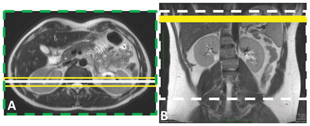
Figure 2.
Schematic of two ASL labeling schemes, including pulsed ASL using FAIR (A) and continuous ASL using pCASL (B). In both schemes, a coronal image is acquired, shown by a solid white line on the axial image (A) and the dashed white line on the coronal image (B). FAIR images are acquired using a slice-selective inversion (yellow box, A) and a non-selective inversion (green dashed box, A). Yellow solid box (B) shows the pCASL labeling plane.

