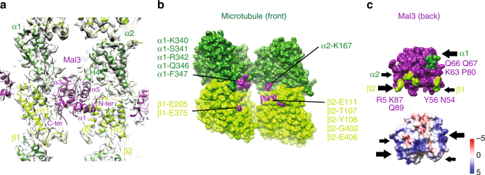
Fig. 6.
Consequences of S. pombe MT architecture for Mal3 binding. a View from the outside of the Sp_tub MT of the Mal3 binding site at the corner of four tubulin dimers, with contacts made to α-tub1 and α-tub2 (dark green), β-tub1 and β-tub2 (light green). b Mal3 footprint on the MT surface with polar and charged tubulin residues < 4 Å distant from Mal3 colored purple and labeled. c MT-binding surface of Mal3; top, polar and charged Mal3 residues < 4 Å distant from the MT colored in green and labeled; bottom, charge distribution of the Mal3 MT-binding surface. The black arrows indicate the four contact points of Mal3 with the MT

