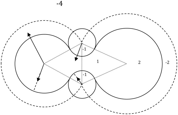
Figure 1.
Grid point labeling scheme in the numerical SES surface definition. Here -4 stands for grid points in the bulk solvent; -2 stands for grid points within SAS spheres if not overwritten below; 2 stands for grid points within VDW spheres; 1 stands for grid points within bicones (shown as the fine dashed triangles) formed by overlapping SAS spheres if not overwritten below; -1 stands for grid points accessible to solvent probes placed on the solvent accessible arcs that are formed by overlapping SAS spheres. The Stern lay is omitted for clarity.

