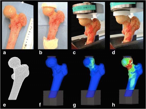
Fig. 1.

Process of mechanical testing and finite element analysis. A proximal femur is sawed 12 cm distal from the tip of the greater trochanter, sloping 20° in the coronal plane to the shaft axis (a). The distal 3 cm of the specimen is fixed using resin cement and a ‘resin cap’ is placed on the femoral head (b). The force is applied at a fixed vertical displacement (c) until the proximal femoral fracture occurs (d). The model of the proximal femur is made (e), is angled and fixed at the distal end with a resin cap on the femoral head (f). A compressive load was applied (g) until predicted fracture (h)
