
Figure 4.
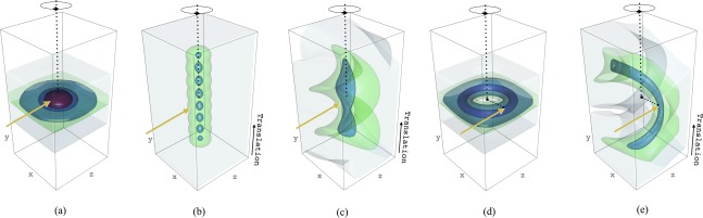
Effect of the dose distribution on the chosen exposure strategy modelled in RADDOSE‐3D. Dose contouring levels have been shown at 0.0001 MGy (grey), 5 MGy (green), 10 MGy (light blue), 20 MGy (dark blue) and 30 MGy (red), using R (www.r-project.org). In each simulation, the crystal rotation axis (in black) and incident beam direction (in yellow, coincident with the z axis) are shown. Unless otherwise stated, each dose distribution is generated following a 360° rotation over a total exposure time of 100 s. In (a) the crystal rotation axis and incident beam direction intersect. In (b) the crystal undergoes a series of eight 360° rotations, each lasting 100/8 = 12.5 s, intersected by a series of 20 µm translations of the crystal parallel to the rotation axis to spread the dose across the crystal volume. In (c) the crystal rotation axis and incident beam direction intersect, however the crystal is continuously translated along the rotation axis at a rate of 0.2 µm/°. In (b) the crystal rotation axis has been offset by 30 µm relative to the incident beam direction. In (e) the rotation axis is offset by 30 µm relative to the beam direction, and the crystal is also continuously translated along the rotation axis at 0.2 µm/°. In all simulations a cuboid crystal has been modelled with dimensions x = 100 µm, y = 200 µm and z = 100 µm. The beam has been modelled as Gaussian shaped (FWHM: 20 µm × 20 µm), with energy 12.4 keV, flux 5 × 10¹¹ ph/s, and a large 1 mm × 1 mm rectangular collimation in order to ensure the full crystal is continuously bathed in the beam for each simulation.