Fig. 1.
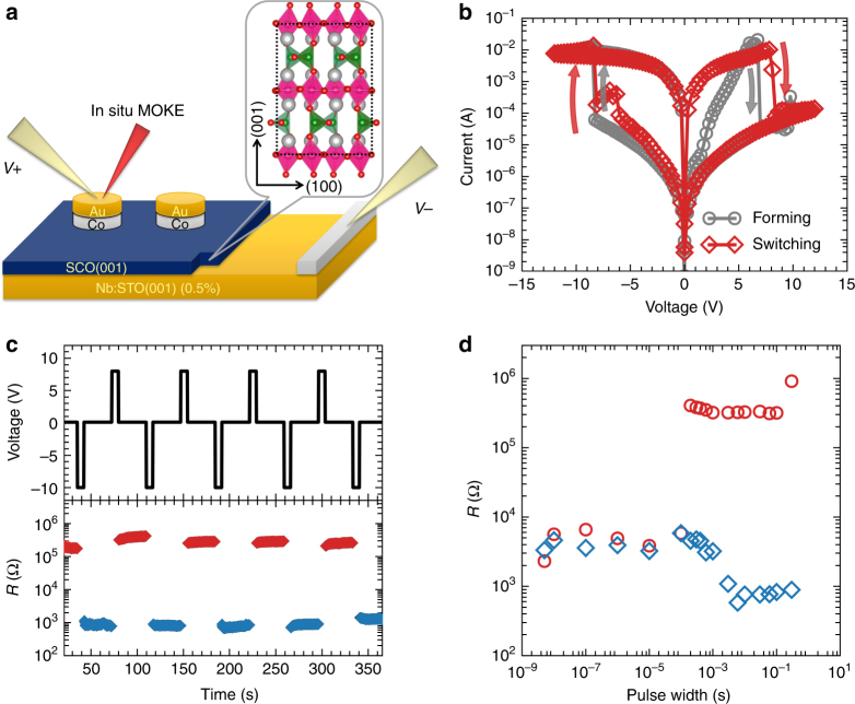
Device configuration and resistance switch in Co/SrCoO2.5. a Schematic diagram of the device configuration with the Co/SrCoO2.5 heterostructure for the in situ resistance switch and MOKE measurements. The electrodes are fabricated into round shape with diameter from 20 to 200 μm. The inset illustrates the crystalline model of SrCoO2.5, where the silver and red balls represent the Sr and O atoms, respectively. The Co–O tetrahedral and octahedral ligands are labelled by green and pink polyhedra, respectively. b I–V characteristic curves of the device showing bipolar resistance switch behavior. c Memory repetition action based on the bipolar resistance switch. The upper panel shows the pulse sequence, while the lower panel shows the corresponding resistance during the reading. The red and navy blue dots represent the readout of the high-resistance states and low-resistance states, respectively. The reading voltage was fixed at +0.1 V. d Resistance switching dynamics with variable pulse durations, where circles and diamonds demonstrate the resistance after positive and negative pulses, respectively

