Fig. 4.
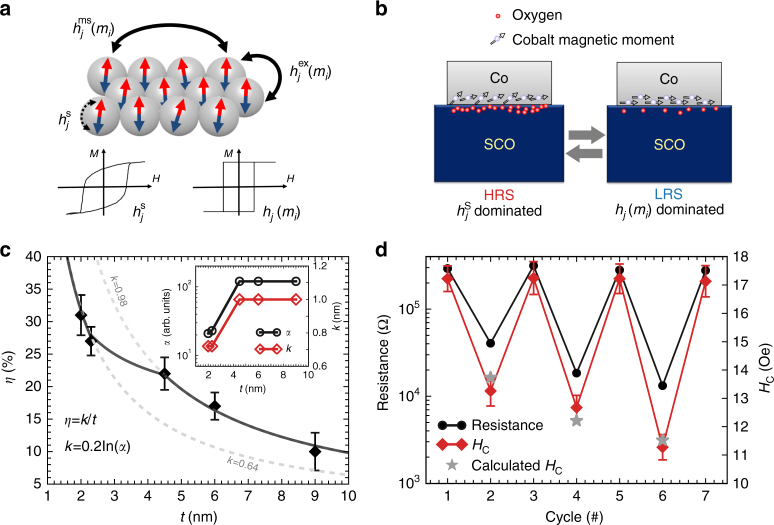
Magnetoelectric coupling via interfacial oxygen ion gating. a Schematic diagram of magnetic interactions in granular thin films. The hysteresis loops represent the extreme cases when intrinsic spin flipping and inter-granular exchanges dominate, respectively. b Schematic diagram of the magnetoelectric coupling via the segregated oxygen ionic accumulation-induced pinning effect and magnetic anisotropy at the interface, where the intrinsic magnetic flipping field is enhanced for the high-resistance state (HRS). c Co thickness (t) dependence of the magnetoelectric coupling for Co/SrCoO2.5 heterostructures. η is calculated by as mentioned above, while the fitting function is defined as η = k/t. The inset shows the correlation between the coercive field modulation and the ON/OFF ratio of the resistance switch. The error bar is calculated from the standard deviation of results obtained in five different devices. d Magnetoelectric coupling with control of oxygen ion gating. The device is set to HRS at the beginning, and then different current limits are set to create the low-resistance state (LRS) with varied resistance values. For each LRS, the coercive field (HC) was obtained through the measurement of the magnetic hysteresis. The star symbols represent the calculated HC values from the ON/OFF ratio during the resistance switch. The error bars indicate the standard deviation from 10 measurements under an identical resistance state

