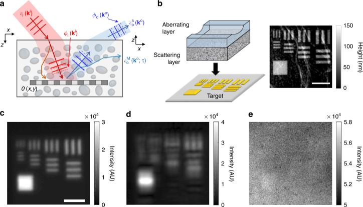
Fig. 1.
The effect of scattering and sample-induced aberrations in the reflectance imaging. a Description of sample-induced aberrations in the illumination and imaging paths. The phase of the unscattered component of an incident wave with transverse wavevector is retarded by , and that of the reflected wave from the target object is retarded by . and stand for single- and multiple-scattered waves. O(x,y): amplitude reflectance of a target object. b Layout of the phantom sample. An asymmetric aberrating layer made of a clean PDMS block with a cylindrical groove was placed on the top of a 7l s-thick scattering layer. A resolution target was placed underneath the scattering layer. The gray scale image is the topography of the target measured by atomic force microscopy. Scale bar, 4 μm. Color map, height in nanometers. c Incoherent image of the target without the scattering and aberrating layers. The image was recorded in the reflection geometry, and light emitting diode (λ = 780nm) was used as a light source. Scale bar, 4 µm. d, e Same as (c), but with an aberrating layer and with both the scattering and aberrating layers, respectively. Color bars in (c–e), intensity in arbitrary unit

