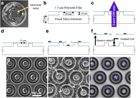
Fig. 1.

Fabrication process and application of cell patterning stencil. a Photograph of the purpose-built fixture (shown inside a 35 mm petri dish) used to secure the polymer thin-film to the microwell array substrate. The microwell array is inside the central reservoir under the polymer film (arrow). b Enlarged cross-sectional diagram of a single microwell (80 μm inner diameter) from the microwell array substrate. The polymer thin-film (blue) is secured across the top of the microwells. c Laser is focused onto the surface of the thin-film and aligned with the center of each microwell. d Thin-film stencil with 35 μm laser fabricated pore aligned with underlying microwell. e Traditional random seeding is used; cell suspension is deposited onto the thin-film polymer stencil. Cells (blue ovals) settle onto the stencil surface and through the pores into the microwells below. f After cell attachment and spreading, the stencil is removed from the substrate revealing spatially-patterned cells. g Phase-contrast image of the stencil substrate prior to cell seeding (equivalent to panel d diagram). h Phase-contrast image of the stencil and substrate after cell seeding (equivalent to panel e). Arrows indicate cells inside microwells, arrowheads indicate cells adhered to the stencil. i Composite fluorescent image of cell nuclei and phase-contrast image of the microwell array substrate after removal of the stencil (equivalent to panel f)
