Abstract
A tightly focused pulsed laser beam can locally modify the crystal structure inside the bulk of a scintillator. The result is incorporation of so-called optical barriers with a refractive index different from that of the crystal bulk, that can be used to redirect the scintillation light and control the light spread in the detector. We here systematically study the scintillation light transport in detectors fabricated using the Laser Induced Optical Barrier technique, and objectively compare their potential performance characteristics with those of the two mainstream detector types: monolithic and mechanically pixelated arrays. Among countless optical barrier patterns, we explore barriers arranged in a pixel-like pattern extending all-the-way or half-way through a 20 mm thick LYSO:Ce crystal. We analyze the performance of the detectors coupled to MPPC arrays, in terms of light response functions, flood maps, line profiles, and light collection efficiency. Our results show that laser-processed detectors with both barrier patterns constitute a new detector category with a behavior between that of the two standard detector types. Results show that when the barrier-crystal interface is smooth, no DOI information can be obtained regardless of barrier refractive index (RI). However, with a rough barrier-crystal interface we can extract multiple levels of DOI. Lower barrier RI results in larger light confinement, leading to better transverse resolution. Furthermore we see that the laser-processed crystals have the potential to increase the light collection efficiency, which could lead to improved energy resolution and potentially better timing resolution due to higher signals. For a laser-processed detector with smooth barrier-crystal interfaces the light collection efficiency is simulated to >42%, and for rough interfaces >73%. The corresponding numbers for a monolithic crystal is 39% with polished surfaces, and 71% with rough surfaces, and for a mechanically pixelated array 35% with polished pixel surfaces and 59% with rough surfaces.
1. Introduction
With the recent development of laser induced optical barriers (LIOB), and sub-surface laser engraving (SSLE) techniques, we now have a new category of scintillation detectors whose features fall in between those of the monolithic and the mechanically pixelated scintillators. These techniques have found their way in a variety of medical imaging applications including Positron Emission Tomography (PET) (Moriya et al 2010, Sabet et al 2012a, Hunter et al 2015, Sabet et al 2016a, Uchida et al 2016, Bläckberg et al 2016b), Single Photon Emission Computed Tomography (SPECT) (Sabet et al 2016b), and Computed Tomography (CT) (Bläckberg et al 2016a). In LIOB a high power pulsed laser is tightly focused inside the bulk of a scintillator crystal, causing a local modification of the crystal structure. The modification is manifested by a change in refractive index (RI) of the material, where the modified region will have a refractive index lower than that of the unmodified crystal. This is in contrast to other reports that used the SSLE technique to create microcracks in the crystal bulk. The lowest achievable RI value is 1.0, corresponding to void formation in the crystal. The modifications are here referred to as optical barriers (OB), and their size, shape, and refractive index depend on the crystal material as well as the laser parameters (i.e. pulse energy, duration, and repetition rate) and the delivery optics that are used during processing. Due to the index mismatch with the crystal bulk the barriers may redirect the scintillation light inside the crystal, and as a result they can be used to control and manipulate the light spread in the detector. Many closely packed optical barriers can form a wall acting similarly to the reflectors inserted in a mechanically pixelated array. The reflectivity of the created wall will depend on the characteristics of individual barriers as well as on how densely these are packed.
While the LIOB technique has been reportedly used for medical imaging applications, there is not much detail with regard to scintillation light transport in laser-processed crystals and how they compare with the two main detector types: monolithic crystals and mechanically pixelated arrays. Furthermore, the nature of the interactions between the laser light and the crystal structure causing the modifications have been poorly explored, and not investigated systematically, and neither have the physical properties of the resulting optical barriers. In this paper, we report on light transport studies of Cerium-doped lutetium yttrium orthosilicate (LYSO:Ce) crystals, which is the mainstay scintillator material for PET. The ultimate goal of this work is the fabrication of a high-sensitivity and high spatial resolution LYSO:Ce detector with depth of interaction (DOI) information and single-side readout, which is demanded for high resolution small animal PET imaging. The small gantry size in these systems, compared to whole body PET, increases the probability of oblique angles of incidence of the gamma rays on the detector face, which will increase the severity of the parallax error caused by mapping all events to the center of each crystal. There are a number of different approaches, (Peng and Levin 2010, Ito et al 2011), that are proposed to obtain DOI information to compensate for the parallax error, including double side readout, phoswich detectors, statistical positioning algorithms for monolithic crystals (Miyaoka et al 2008, Ling et al 2007b), and analysis of the signal rise time (Wiener et al 2013). Work has also been done with more complex reflector arrangements employed to encode the light spread in the detector block as a function of DOI (Ito et al 2010). We are exploring the potential of extracting DOI information from the light response functions of scintillators containing optical barriers. Similar work was previously done for monolithic crystals (Lerche et al 2005), as well as for pixelated detectors with depth dependent light sharing (Yang et al 2009). Unlike many other complex detector arrangements that are proposed, our approach has the potential of providing a detector with DOI capability and high transversal resolution in a cost-effective manner, without adding to the system complexity.
We propose to use the flexibility of the LIOB technique to create a pattern of optical barriers inside the scintillator volume in order to spread the scintillation light over multiple photodetectors in such way that both transverse and DOI resolution can be achieved. The fact that the optical barriers can be placed virtually anywhere, in any pattern, inside the crystal, and even in the entrance windows of the photodetector elements and the light guide, is the key area that differentiates the laser-processed detectors from the standard monolithic and mechanically pixelated ones.
A scintillator detector fabricated using LIOB falls between the two extremes of a monolithic detector with no incorporated structures, and a mechanically pixelated array that relies on near complete optical isolation between pixels, as illustrated in figure 1.
Figure 1.
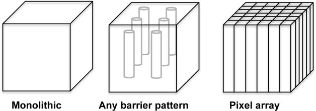
Schematic figure showing how a detector fabricated using the LIOB technique is positioned between the two extremes of a monolithic detector block and a mechanically pixelated array. The optical barrier pattern shown in this figure is just an example aimed to illustrate the flexibility in the shapes that can be introduced into the crystal using the LIOB technique. It is apparent that virtually any pattern of optical barriers can be incorporated into the detector.
Among the huge barrier pattern space available thanks to the flexibility of the LIOB technique, in this work we only study the light transport in detectors with simple pixel-like optical barrier patterns, extending all the way, or half way through a LYSO:Ce crystal. We then compare the expected detector performance of these laser-processed detectors with that of a monolithic crystal and a pixelated array under the same overall constraints. Given that the optical barriers allow for some amount of cross talk between pixels, the light spread function of a detector with optical barriers has the potential to combine the DOI dependency inherent to a monolithic detector with the transversal resolution of a pixelated array.
2. Materials and methods
All simulations presented in this paper were performed using the Monte Carlo code DETECT2000 (Cayouette et al 2003). In the following sections, we describe the different detector types and configurations that were implemented, the simulation parameters used to model the detectors, and finally how the simulations were set up in order to study and compare the performance of each of the detector types.
2.1. Scintillator detector types
We have studied three scintillator detector types: monolithic detectors, mechanically pixelated arrays, and laser-processed scintillators containing optical barriers. As discussed in the introduction of this paper, one can envisage the first two types as two distinct categories, and the latter as a new category combining features of the other two.
In all studies presented in this work, the total scintillator detector dimension was kept constant at 25.4×25.4×20.0 mm3 to match the cross-section of the photodetector array described in section 2.3. Furthermore, in all cases the side- and entrance surfaces of the detector were wrapped in an external diffuse reflector with a reflection coefficient of 0.98, corresponding to 3 layers of Teflon tape (Janecek and Moses 2008), and the exit surface coupled to the photodetector array was polished.
2.1.1. Monolithic crystal
For the monolithic detector, the roughness of the outer crystal surfaces was varied to simulate both polished and unpolished detectors.
2.1.2. Mechanically pixelated crystal array
The mechanical array was simulated as 21×21 individual crystals, each with a dimension of 1.0×1.0×20.0 mm3, individually wrapped in Teflon tape. The dead space between the pixels was set to 0.2 mm, and no photon transport was modeled in the reflector material. The roughness of the outer surfaces of each individual pixel was varied.
2.1.3. Laser-processed crystal
Two optical barrier patterns were simulated, as shown in figure 2. They correspond to a detector with optical barriers in a pixel-like pattern extending all the way through the crystal thickness (a) and one with barriers only in the top half of the crystal (b). In both cases the barriers are arranged with 1 mm separation forming a 24×24 array where each pixel-like volume has a cross-section of 1.0×1.0 mm2. For this detector type the outer crystal surface was kept polished, and the roughness of the barrier-crystal interface as well as the barrier RI were varied.
Figure 2.

Schematic side views of the laser-processed detector configurations, and illustrations of the simulation setups. In (a) the optical barrier pixel pattern extends all the way through the 20 mm crystal thickness, and in (b) only the top half (10 mm) is processed. Geometry (a) is shown with light guide, but was also simulated without light guide. Light response functions and line profiles are generated along the central and edge pixel rows in the crystal as shown in (c). Due to symmetry, flood maps are only generated for one quarter of the crystal area shown in gray in (d).
2.2. Light guide
The mechanically pixelated array was simulated with a 1 mm thick light guide (RI=1.5) coupled to the photodetector. The laser-processed geometry (a) was simulated with and without such light guide, while the laser-processed geometry (b) as well as the monolithic detector were simulated without light guide. In detector configurations that rely on complete optical isolation between scintillator pixels, such as a mechanically pixelated array, a light guide is needed to spread the scintillation light over multiple photodetector pixels for accurate event positioning, unless one-to-one coupling between each crystal pixel and photodetector pixel is employed. This spread is inherent in a monolithic detector, where a light guide would only serve as a mean to remove the possibility of gamma ray interactions very close to the photodetector plane. As a detector category between these two extremes, a laser-processed detector does not necessarily rely on optically isolated pixels. However, given the similarity of the all-the-way barrier detector to a conventional pixelated array we chose to simulate this configuration both with and without the light guide.
2.3. LYSO:Ce crystal
The LYSO:Ce crystal was simulated with a refractive index of 1.82 at 420 nm. An optical absorption length of 40 cm was used, and scattering of the optical photons within the crystal bulk was not considered (i.e. infinite scatter length). These values were chosen based on a literature survey where no clear consensus was found regarding the best values to choose, and the properties have also been shown to vary between crystals from different manufacturers (Steinbach et al 2012). Furthermore, the attenuation is often measured as a single quantity without separating the components of scattering and absorption. Given that our detector modules are relatively small, scattering should not have a significant impact and the absorption length used is found within the range of values used and measured by others (Berg et al 2015, García et al 2007, Ogata et al 2014, van der Laan et al 2010, Zhang et al 2013).
2.4. Photodetector array
We used a simplified model of Hamamatsu S13361-3050AE-08 Multi-Pixel Photon Counter (MPPC). This device is an 8×8 MPPC array of 3.0×3.0mm2 pixels with 3.2 mm pixel pitch. The array has a 0.1 mm thick entrance window with a refractive index of 1.55 (Hamamatsu Photonics K.K. 2016). In our simulations, the optical photons intersecting with the active area of the MPPC pixels were treated as “counted” and those reaching the inter-pixel dead space as “lost”. This setup does not take into account reflections from the dead space or the active surface back into the entrance window and scintillator crystal, but captures the transversal distribution of photons impinging on the photodetector plane.
2.5. Optical barriers
The optical barriers were modeled as 50 μm thick slabs in all simulations reported in this paper. This barrier thickness is based on experimental observations of barrier thicknesses between approximately 20 and 50 μm in LYSO:Ce that was previously reported (Sabet et al 2012a). The size depends on the laser parameters and delivery optics used during the process, as well as on the crystal material. It is noteworthy that no significant difference in light confinement was observed when varying the barrier thickness within this range in the simulations. It should be noted that DETECT2000 is based only on a geometrical optics model (aka ray optics). If the barrier size becomes comparable to the emission wavelength of LYSO:Ce, a wave optics model should be used to study the light transport in the crystal, since diffraction and interference can become significant components.
It is known that the refractive index of the optical barriers differs from that of the crystal bulk, and that its value depends on the laser parameters chosen during processing, as well as on the properties of the scintillator crystal itself. Furthermore, we have shown that the roughness of the interface between the barriers and the unmodified crystal can be controlled to some extent by varying laser parameters (Bläckberg et al 2016a). However, to this date, and to the best of our knowledge, no one has been able to show exactly how different laser parameters are linked to the optical barrier properties. This is especially a complex task given the large laser parameter space in combination with difficulties to use standard methods to measure the barrier properties in thick crystals. In this work we chose a range of RI values and interface roughness values that are possible to achieve based on our prior experimental results (Sabet et al 2014, Bläckberg et al 2016a) and the literature. Given that the RI and the interface roughness are two distinct parameters and not necessarily correlated, all combinations of the two parameters were studied. The RI value was varied from RI=1.0, the lowest achievable value corresponding to void formation in the crystal, up to RI=1.6.
The interface between the optical barrier and the unmodified crystal bulk was described using the POLISH and the UNIFIED surface models implemented in DETECT2000. POLISH corresponds to a perfectly smooth interface where all reflections and refractions are specular around the nominal surface normal. The UNIFIED surface model can be used to describe a range of surface roughness values between a specular and a completely diffuse interface, and also linear combinations between different types of reflections (Levin and Moisan 1996). In this work we have used specular lobe reflection characterized by the σα parameter, which is recommended for simulations of a rough interface between two dielectric surfaces (Moisan et al 2000). The σα parameter corresponds to the standard deviation of a Gaussian distribution of surface normals around the nominal surface normal, and is typically determined by constraining it to surface roughness data. For an interface like the one between an optical barrier and the crystal bulk there is no straightforward way of obtaining such data since the barriers are contained inside the crystal bulk, and placing them close to an edge for easier characterization will affect their properties.
2.6. Simulation setup
For each of the detector types described in section 2.1 we generated one dimensional light response functions (LRFs), as well as flood maps and line profiles as a function of gamma-ray DOI. We also extracted the light collection efficiency for all simulated detector types. Only the light spread from photopeak events where the full gamma-ray energy is absorbed in the first interaction was simulated. This is a simplifying assumption given that a large fraction of the interactions in a PET detector will be due to Compton scatter of the incoming gamma-ray. LYSO:Ce has a light yield of 27-32 photons per keV, which yields about 13800-16300 optical photons for photoelectric absorption of 511 keV gammas. The S13361-3050AE MPPC series have ~37% photon detection efficiency (PDE) at 420 nm. Therefore we started the light transport simulations with 5000 optical photons per gamma-ray interaction and set the quantum efficiency for the modeled photodetector to 1. Hence, the inherent energy resolution of LYSO:Ce was neglected. All simulations were started with different initial seeds, making them statistically independent.
2.6.1. Light response function
The procedure to generate the LRF as a function of DOI consists of beam scans along one central and one edge pixel row, as illustrated in figure 2. An isotropic source of 420 nm optical photons was moved in 0.35 mm steps along the pixel row (3 source locations per pixel). Due to symmetry, events were only generated in half of the detector and the results mirrored to obtain the complete light response function. At each source location 300 gamma events were simulated, resulting in a total of ~150000 events per detector configuration. Statistics beyond this was not found to change the results significantly. The beam scans were repeated at different crystal depths with 3 mm separation in the Z-direction. Because of the discontinuity at z=10 mm in the half-way barrier detectors the Z-separation was set to 2 mm in the center of this detector to avoid photon generation right at the discontinuity. The number of photons detected by each MPPC pixel was recorded as a function of source location, and the results used to generate 1D LRFs as a function of DOI for each of the detector configurations. The width of the light response function was further analyzed to investigate the DOI capabilities of each detector configuration.
2.6.2. Flood map and line profiles
For each detector configuration flood maps were generated as a function of depth by simulating 400 gamma events randomly distributed over the cross-section of each pixel, at the same 7 discrete crystal depths as the light response functions (8 for the half-way barriers). For the monolithic crystal, events were randomly generated over the complete crystal cross-section, with the total number of events per depth equal to the other detector configurations. Due to symmetry events were only simulated in one quarter of the crystal in the XY-directions, as illustrated in figure 2. The total number of simulated events for each detector configuration was ~400000. For the laser-processed detectors as well as the mechanical array the optical barriers and reflectors were treated as dead space and no events were generated in these volumes. We used a simple centroid event positioning estimator on the MPPC signals to generate position histograms and the associated line profiles. While this simple anger logic is not typically used for event positioning in monolithic crystals, we chose this method to make a simple and straightforward comparison between the different detector configurations. Nowadays more sophisticated algorithms, such as Maximum Likelihood (ML) are being used, which could be very well suited for the laser-processed detectors, which we aim to explore in future work.
2.6.3. Light collection efficiency
The light collection efficiency for each detector configuration was determined by averaging the total number of counted photons over all interaction locations simulated for the flood maps. Information regarding where losses occurred (i.e. bulk absorption, trapping, or surface losses) could also be extracted from this data.
3. Results
While we simulated a range of barrier RI values, the majority of the presented results are for RI=1.0, corresponding to that of void as the best-case scenario, and for RI=1.4 as a mid-range value between void and the crystal bulk. In the following sections, LRFs, flood maps and line profiles are shown for each of the three scintillator categories, including the two variations of the laser-processed detector (sections 3.1-3.3). The LRFs were generated by averaging all events from the same source location, and normalizing to the number of emitted optical photons in one event. Normalization to the number of collected photons results in curves with similar shape, but the absolute values differ. The light collection efficiencies for all detector configurations are summarized in section 3.4.
3.1. Monolithic detector
The results for the monolithic detector are summarized in figure 3, as a function of crystal surface roughness. Light response functions for the central and edge rows respectively, are shown for four adjacent MPPC pixels at the central DOI. The FWHM width of the LRF was calculated as a function of DOI and crystal surface roughness, for events taking place in the center of the crystal, as well as along the edge. The values were obtained by fitting with a Gaussian function. It can be observed that regardless of the surface properties of the crystal, the depth dependence of the LRF is almost linear, both for the central part and the edge of the crystal. As expected, the width of the LRF is increasing with distance from the photodetector plane. Flood maps are shown for a polished crystal, as well as a rough one with σα=20°. The discontinuities in the maps are due to the discrete number of interaction depths simulated, where the width of the flood maps increases with increasing DOI. It is also evident that the flat nature of the LRF, especially close to the detector entrance surface, makes event positioning using the simple centroid estimator difficult. Furthermore, a rough outer detector surface results in smaller spread in the flood maps and impaired transversal detector resolution compared to a polished crystal.
Figure 3.
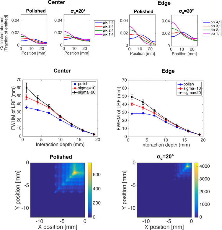
Top: LRF for four adjacent MPPC pixels at a central interaction depth (Z=10 mm), as a function of event location. Results are shown for a polished crystal and a rough one with σα=20°, as well as for central and edge beam scans. Middle: FWHM of the LRF for one central MPPC pixel as a function of DOI and surface roughness. The values are obtained by fitting the LRF at each interaction depth with a Gaussian curve and determination of the FWHM width. The error bars correspond to the 95% confidence interval of the fitting parameter. Results are shown for events simulated in the center of the crystal, as well as along the edge. Bottom: Flood maps for the monolithic crystal with polished and rough side surfaces, respectively. The maps shown are the summation of 7 discrete crystal depths (3 mm separation in Z).
3.2. Mechanically pixelated array
Figure 4 summarizes the results for the mechanically pixelated array. For this detector type, unlike for the monolithic detector, there is no DOI dependence observed in the LRF. Furthermore, the step-like nature of the LRF shows that events from within the same pixel will all be mapped to the center of that pixel. This is in contrast to the LRF for the monolithic detector that, as expected, has a more continuous appearance. The flood maps show that for the polished array all pixels can be well resolved except the edge pixels that are barely separable. For the rough pixel surface, events tend to group to the center of each MPPC pixel, and the edge pixels are completely merged. The same trends are observed both in the central and edge line profiles.
Figure 4.
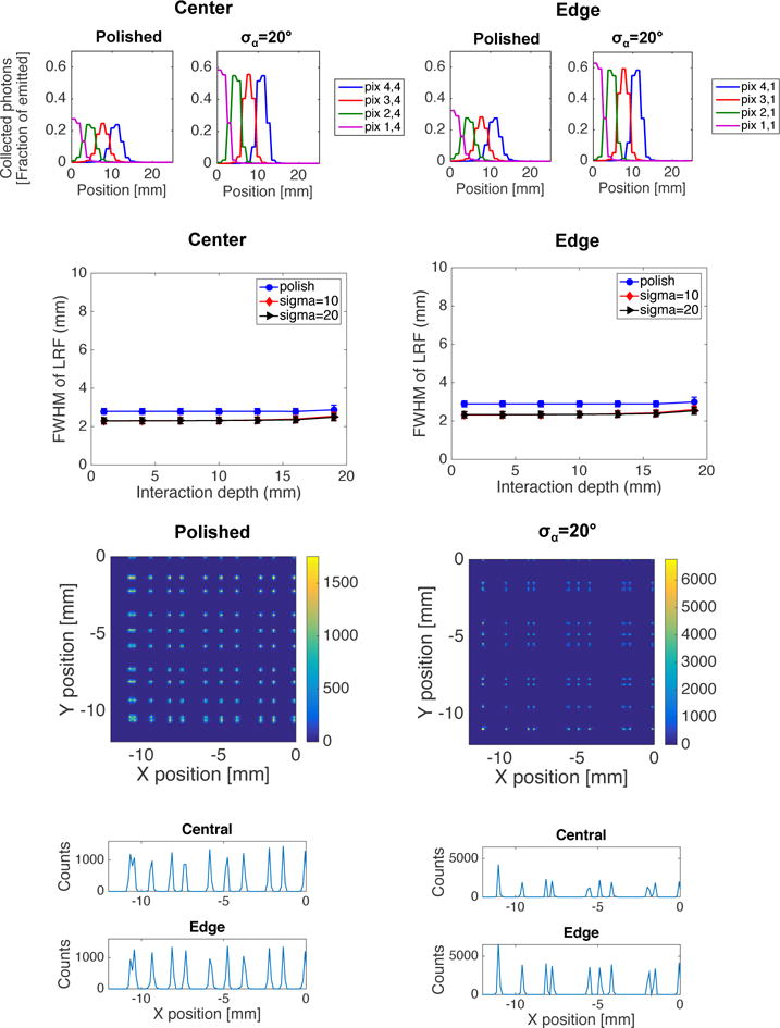
LRF for 4 adjacent MPPC pixels at central interaction depth (Z=10 mm), as a function of pixel surface roughness and location of the beam scan (center or edge). Middle: FWHM width of the LRF as a function of DOI and pixel surface roughness for one central MPPC pixel. The values are obtained by fitting the LRF with a Gaussian curve. The error bars correspond to the 95% confidence interval of the fitting parameter. Results are shown both for central and edge beam scans. Bottom: Flood maps and line profiles for arrays with polished and rough pixel surfaces, respectively. The flood maps are the summation of 7 discrete crystal depths. The line profiles are taken along a central and an edge pixel row respectively. It should be noted that the figure shows one quarter of the crystal in the XY-direction, and hence 10.5 pixels should be seen in the line profiles if all pixels are to be resolved.
3.3. Laser-processed detectors
3.3.1. Optical barriers all the way through the crystal thickness
Figure 5 shows LRFs at one central depth for different RI/barrier-crystal interface combinations. The results are shown both with and without light guide and for beam scans through the center and along the edge of the detector. The LRFs for the polished detectors without light guide are characterized by very sharp slopes and flat tops, indicating that pixels above the same MPPC pixel will be hard to separate. Figure 6 shows the FWHM of the LRF as a function of DOI, barrier refractive index and barrier-crystal interface roughness. For a smooth interface there is no depth dependence regardless of barrier RI, while for the rougher interface the width of the LRF decreases with interaction depth. As expected, this dependence becomes more pronounced when the barrier RI approaches that of the LYSO:Ce crystal, in which case the behavior of the detector will approach that of a monolithic one. The same trends are observed both in the center and along the edge of the crystal, as well as with and without the use of a light guide.
Figure 5.
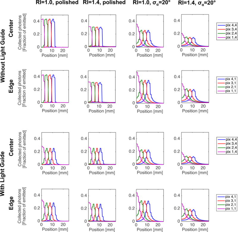
LRFs for four adjacent MPPC pixels at one central interaction depth (Z=10 mm), as a function of barrier RI and barrier-crystal interface roughness. Results are shown for central and edge beam scans, and with and without a 1 mm light guide between the crystal and the MPPC array.
Figure 6.
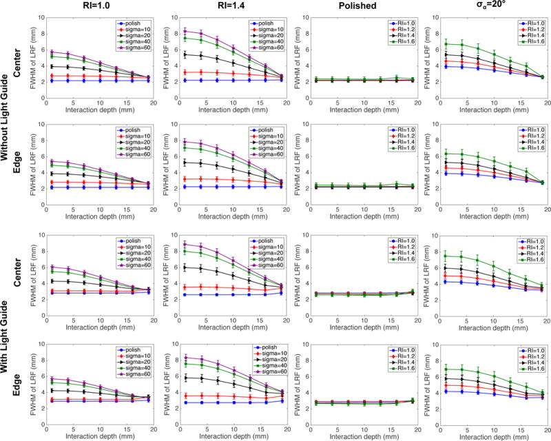
FWHM of the LRF for one central MPPC pixel as a function of DOI and quality of the optical barriers. The values were obtained by fitting the LRF at each depth with a Gaussian function. The error bars correspond to the 95% confidence interval of the fitting parameter. Results are shown with and without a light guide and for beam scans along the center and edge of the detector.
Figure 7 shows flood maps and line profiles produced using the centroid estimator for different RI-interface roughness combinations, with and without the use of a light guide. It is apparent a smooth barrier-crystal interface results in high light confinement, and that a light guide is needed for pixel separation regardless of barrier RI in this case, as was indicated also by the shape of the LRFs. For a rough barrier-crystal interface and barrier RI=1.0, all 12 pixels except the edge pixels may be resolved even without a light guide. This is true both in the center of the detector and along the edge. A light guide does however slightly separate the edge pixels, and improves the overall transversal resolution. The depth dependence in the flood map is more pronounced for RI=1.4 with a rough interface, while the transversal resolution is impaired compared to RI=1.0, especially at the crystal edges. Figure 7 further shows the FWHM dependence of the LRF for each of the 8 configurations. For a rough interface, DOI information can be extracted regardless of barrier RI and both with and without a light guide, while for a smooth interface the FWHM is always independent of DOI. Based on this information and the superior transversal resolution of the detector with rough barrier-crystal interface and barrier RI=1.0, we chose to study this detector type (with light guide) in more detail. Figure 8 shows flood maps and line profiles at each individual interaction depth for this configuration. The line profiles show that all 12 pixels can be resolved at each depth, both in the center and along the detector edge, except for very close to the photodetector plane where the two edge pixels are merged.
Figure 7.
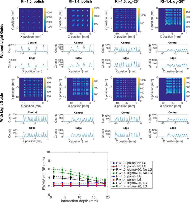
Top: Flood maps and line profiles for laser-processed detectors with barriers all the way through the crystal thickness. The flood maps contain 7 discrete interaction depths, and line profiles are shown for one central and one edge pixel row. Results are shown both with and without a light guide and for RI=1.0 and 1.4 and polished and rough barrier-crystal interfaces. Given that a quarter of the crystal is shown in the figure, 12×12 pixels should be resolved for perfect pixel separation. Bottom: FWHM width of the LRF as a function of depth for each of the configurations shown in the top part of the figure.
Figure 8.
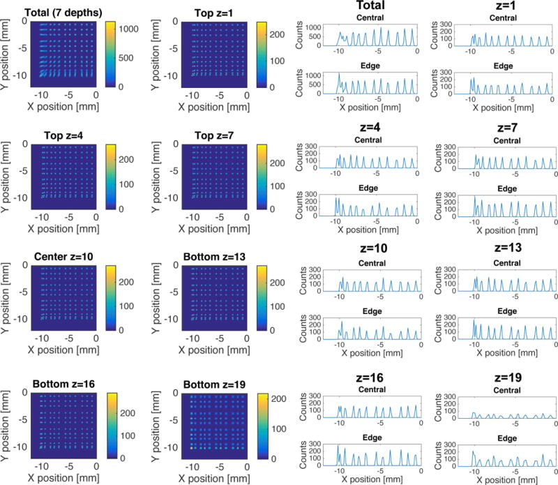
Flood maps and line profiles at each individual interaction depth in the detector with barriers all the way through the crystal thickness, barrier RI=1.0 and barrier-crystal interface roughness characterized by σα=20° coupled with a light guide to the MPPC array.
3.3.2. Barriers in top 10 mm
Figure 9 shows the LRF for a detector with optical barriers half way through the crystal thickness, as a function of DOI, barrier RI, and barrier-crystal interface roughness. The same figure contains FWHM curves showing how the LRF width varies with DOI. These curves have a more complex shape, compared to the other detector types, caused by having different detector configurations in the top and bottom half of the scintillator crystal. For events within the unprocessed part of the detector the LRF width increases with distance from the photodetector plane, similarly as in the monolithic detector. For events within the pixelated region there is only very marginal depth dependence when the interface is smooth. However, for a rough interface there is clear depth dependence also in this region where the LRF width becomes narrower with increasing distance from the photodetector. These trends are very similar both in the center and along the edge of the crystal. Figure 10 shows flood maps for all interaction depths combined, as a function of interface roughness and barrier RI. The flood maps all have a complex appearance due to the different detector properties in the top and bottom half and the discrete number of interaction depths. In all cases one can see that the central pixels are well resolved in parts of the detector while the side pixels are merged, and the performance in general seems better with a rougher interface. Figure 10 also shows the corresponding FWHM curves for the same four cases. Given that most gamma ray interactions will take place in the top part of the detector, DOI information is most important in this region. Based on these observations we chose to study the case of barrier RI=1.0 and a rough interface in more detail. Figure 11 shows flood maps for this detector at each individual interaction depth, together with line profiles from the top half of the detector. In this region, all but the edge pixels can be resolved, both in the center and along the detector edge. The flood maps in the bottom half resembles those of a monolithic detector, and hence line profiles produced using anger logic are not meaningful at these depths.
Figure 9.
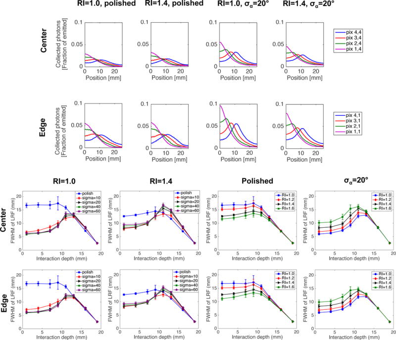
Top: LRF for four adjacent MPPC pixels at one central interaction depth (Z=11 mm), as a function of barrier RI and roughness of the barrier-crystal interface. The results are shown for one beam scan through the center of the detector, and one along the edge. Bottom: FWHM values obtained by fitting the LRF with a Gaussian function, shown as a function of DOI, barrier RI and barrier-crystal interface roughness. The results are shown for beam scans though the center and along the edge of the detector.
Figure 10.
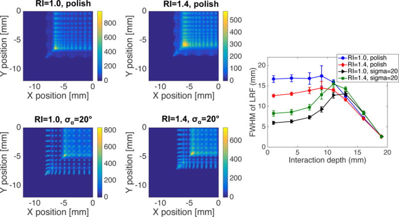
Left: Flood maps containing 8 discrete interaction depths, shown for four RI/interface roughness combinations. Right: The corresponding FWHM curves indicating the DOI dependence of each configuration.
Figure 11.
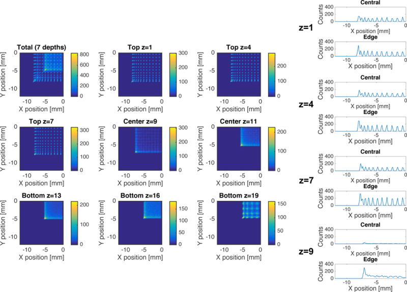
Flood maps and line profiles for each individual interaction depth for a detector with barriers half way through the detector, barrier RI=1.0 and barrier-crystal interface roughness given by σα=20°.
3.4. Light collection efficiency
Table 1 summarizes the light collection efficiency and the nature of the light losses in each of the simulated detector configurations. The numbers quoted are the average over all events in the flood map simulations. One can see that the light collection efficiency is increased for detectors containing optical barriers compared to both the monolithic detector block and the mechanically pixelated array. Furthermore, it can be noted that the losses for a monolithic detector, as well as a laser-processed one, are dominated by optical absorption in the crystal bulk, while for the mechanical array the losses occur mainly at surfaces due to non-perfect reflectors. The reason is a dramatic increase in number of surface reflections in the high aspect ratio pixels compared to the monolithic detector block. Figure 12 shows how the light collection efficiency varies with the reflection coefficient of the reflector surrounding each pixel in the mechanical array. For unpolished pixels the light collection efficiency is strongly dependent on the reflection coefficient, while for polished pixels there is no such dependence. In the latter case the decrease in surface losses is compensated by an increase in bulk losses due to absorption. Table 1 further reflects how the light collection efficiency varies over the detector volume, and noteworthy is that the uniformity of the light collection efficiency is better in the monolithic detector compared to the mechanical array. The latter has higher light collection efficiency closer to the photodetector, and also shows great variations depending on where the interaction point is with respect to the active/dead areas of the MPPC array. For the laser-processed detectors the configuration with optical barriers all way through the crystal thickness has more uniform light collection efficiency compared to the configuration with barriers only half way through the crystal, and the overall uniformity in the laser-processed detectors is between the monolithic detector and the mechanical array.
Table 1.
Light collection efficiency and types of losses in the studied detector configurations. “Other losses” refer to photons being absorbed at reflectors, hitting the dead space of the photodetector array, escaping the geometry or being internally trapped. The two latter contributions are minor in all cases. For the monolithic detector and the pixelated array “Polish” and σα = 20° corresponds to the outer surfaces of the crystal block as well as the individual pixels. For the geometries containing optical barriers the outer crystal surface is polished in all cases and surface roughness specifications correspond to the barrier-crystal interface. The results are shown with light guide for the mechanical array and the all way barriers, and without for the other geometries. The uncertainties given in the “Counted” columns reflect the standard deviation in the number of counted photons over all gamma-ray events used to calculate the average light collection efficiency.
| Polished
|
σα = 20°
|
|||||
|---|---|---|---|---|---|---|
| Counted (%) | Absorbed (%) | Other (%) | Counted (%) | Absorbed (%) | Other (%) | |
| Monolithic | 39.5 ± 0.8 | 48.5 | 12.0 | 71.6 ± 0.9 | 17.9 | 10.5 |
| Mechanical array | 35.5 ± 1.2 | 31.2 | 33.3 | 59.1 ± 7.1 | 13.0 | 27.9 |
| OB all way, RI=1.0 | 42.5 ± 1.2 | 46.2 | 11.3 | 74.3 ± 2.6 | 14.0 | 11.7 |
| OB all way, RI=1.4 | 45.2 ± 1.4 | 42.5 | 12.4 | 76.7 ± 1.2 | 11.4 | 11.9 |
| OB 10 mm, RI=1.0 | 45.2 ± 1.2 | 43.3 | 11.5 | 73.6 ± 3.9 | 15.1 | 11.3 |
| OB 10 mm, RI=1.4 | 46.3 ± 1.3 | 41.5 | 12.2 | 73.6 ± 4.2 | 15.0 | 11.5 |
Figure 12.
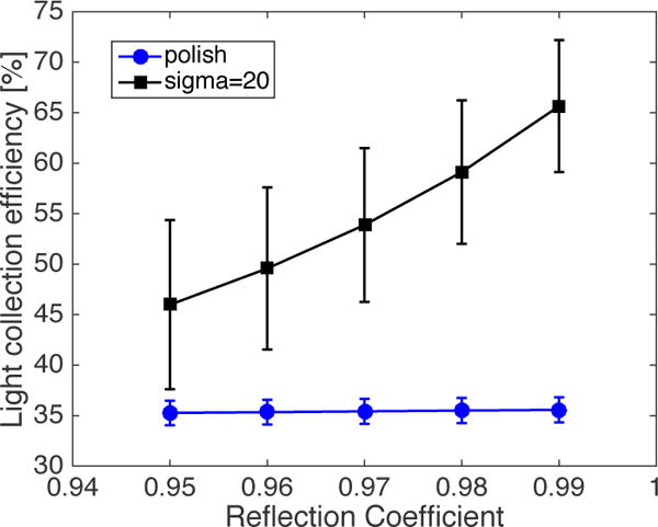
Light collection efficiency as a function of reflection coefficient of the diffuse reflector in a mechanically pixelated array. The results are shown for polished and rough pixel surfaces, and the error bars reflect the variation in light collection efficiency over the detector volume.
4. Discussion and conclusions
The main objective of this work is to provide a baseline of expected performance characteristics of laser-processed detectors with simple pixel-like patterns compared with the performance of the standard detector types used in nuclear medicine imaging today. Therefore we have focused on exploring the basic barrier patterns rather than providing a final detector design. It is apparent that the laser-processed detectors need to be further optimized to achieve the desired performance for a specific end-application. Additionally, similar to other detector types that typically suffer from performance degradation near the detector edge, optimization of the barrier patterns is required to solve this issue for laser-processed detectors. One way of solving this could be to fabricate barriers with different properties for the edge pixels in order to separate them. In this paper we chose a 64 channel MPPC array for sampling of the scintillation light. This may be considered as a large number of channels for a full-ring PET system, but given the similarities between the all the way barrier detector and the mechanical array in terms of transversal resolution, standard channel reduction techniques could potentially be employed to reduce the number of readout channels which is a subject of future work.
Through simulation studies, we have shown that the behavior of a laser-processed LYSO:Ce detector containing optical barriers falls between that of the two extreme detector types, monolithic and mechanically pixelated arrays. The behavior of a laser-processed crystal can be tailored to be closer to a monolithic crystal or a pixelated detector array, thanks to the huge laser parameter space as well as barrier pattern space that the LIOB technique can offer. Among countless number of optical barrier patterns, we selected two simplified versions that are easy to implement experimentally and easy to follow conceptually. The all-the-way barrier pattern resembles the mechanically pixelated array type and the top-half barrier pattern is similar to work that has been explored elsewhere (Kaul et al 2013, Gonzalez-Montoro et al 2017).
It should be noted that the presented simulations were performed under certain simplifying circumstances, however we do not anticipate that these will significantly change the results or the conclusions drawn. We have neglected the inherent energy resolution of LYSO:Ce and simulated a fixed number of 5000 optical photons per gamma ray interaction. However, the source will be isotropic in either case, and a lower number of optical photons will not affect the event positioning, which is the main performance characteristic studied in this work. In addition, we have only simulated photopeak events where the full gamma ray energy is deposited in one location. The effect of Compton scattered events, which constitutes a large fraction of the interactions in a real detector, will be the subject of a different study and can be explored in conjunction with strategies to estimate the first location of gamma-ray interaction. Finally, we have used a simplified implementation of the MPPC array where no photons are reflected back into the geometry from the dead spaces of the array. Hamamatsu has communicated that ~30% of the photons are in fact reflected back from the dead spaces. They have however not given any detailed information regarding the angular dependence of the reflectivity, or the characteristics of the reflected light. We carried out additional simulations to estimate the effect of this reflection type. We arrived at a difference of less than 4% in the light collection efficiency of the laser-processed detectors and similar effects across all detector types, and therefore concluded that the results presented here are valid with or without including the photon reflection from these inter-MPPC gaps.
We first simulated the monolithic and the pixelated array detector types in DETECT2000, as these constitute the mainstay in imaging applications and have been in use for decades. Even though other structured scintillator types have been developed, such as microcolumnar detectors (Nagarkar et al 1998, Sabet et al 2012b), and scintillators that are grown into pixel shapes (Sabet et al 2013, Zhao et al 2015), we focused this study on the most common detector types for nuclear medicine applications. These initial simulations helped us debug our code and setup baselines for the new detector designs fabricated using the LIOB technique.
The results presented in figure 3 represents the LRF and its depth dependence as well as flood maps for a monolithic LYSO:Ce detector. As expected, the LRF and its width is a function of gamma-ray interaction depth, and our results are in good agreement with those reported elsewhere (Kaul et al 2013, Ling et al 2007a, Lerche et al 2005, Tavernier et al 2005). We also notice that the flood map is more expanded when using a polished monolithic crystal compared with a crystal with a rougher surface finish. The LRF width has a linear behavior, which bodes well with the fact that thin monolithic crystals are a great choice when DOI is needed and high transverse spatial resolution is not demanded. As expected, the detector spatial resolution is degraded near the edge area due to the so-called edge effect that is more pronounced in these detector types when using a centroid positioning estimator, compared to pixelated detectors.
The corresponding results for a mechanically pixelated detector array are shown in figure 4. Here no DOI is achievable with single-side readout and the centroid positioning algorithm. The detector transverse resolution is better than in a monolithic detector, and all pixels in the array are resolved in the flood maps and line profiles. Note that the sharp slope of the LRFs in the top row of the figure manifests this superior transverse resolution when using the centroid positioning algorithm. The high transversal resolution makes this detector type the backbone of the majority of the high spatial resolution imagers where the detector thickness can be increased to enhance the system sensitivity with little effect on the resolution. On the other hand, given that no DOI can be extracted in a single-side readout scheme, a thick detector leads to image blurring in the FOV periphery, especially in small animal PET systems.
The laser-processed detector with optical barriers all the way through the crystal thickness visually resembles the pixelated array type, but shows a behavior that is a combination of that of the monolithic detector and the pixelated array, depending on the barrier properties. In figure 6, we observe that when the barrier RI equals to that of air (RI=1.0) and the barrier-crystal interface is smooth, no DOI information can be extracted, regardless of existence of a light guide. A light guide will, however, spread the light over multiple MPPC pixels and can be used to avoid merging pixels in the flood maps. This behavior can be most useful when high light channeling in each of the pixel-like elements is demanded. Figure 6 also shows that in the case of rough barrier-crystal interfaces, there is a clear depth dependency, and a continuously linear DOI can be extracted from the width of the LRF. The flood maps and line profiles in figures 7 and 8 show that also excellent transverse spatial resolution can be achieved with a rough barrier-crystal interface. The transverse resolution is superior when the barrier RI equals 1.0 and a light guide is used. This configuration was considered the most promising one and was studied in more detail, showing that all pixels can be resolved regardless of interaction depth, except for events very close to the photodetector plane.
In the detector with optical barriers only in the top half of the crystal, the LRF gives subtle DOI information when the barrier-crystal interface is smooth. However the DOI dependency of the LRF becomes stronger when this interface is rough, following a similar trend compared with the detector with all-the-way barrier pattern (see figure 9). We observe a complex DOI response in that when the barrier RI is 1.0 and the barrier-crystal interface is rough, the LRF width linearly increases with DOI until a tipping point at 13 mm after which it starts to decrease sharply with interaction depth. With RI of 1.4, there is larger light spread as expected but the tipping point in the plot with different barrier-crystal interface roughness takes place at a crystal depth of 11 mm. In the two linear areas of the LRF width curve (before and after 13 mm crystal depth for barrier RI=1.0), we can observe that for example the LRF width is the same for interaction depths of 7 and 13 mm. However, the LRF signals of the MPPCs have different values for these two cases, which can be used to distinguish between gamma-rays interacting at 7 or 13 mm depths. Figure 9 further shows that when the barrier-crystal interface is rough, a wide range of barrier RIs can be used to extract multiple DOI levels, a flexibility that can be used to fine-tune the transverse vs DOI resolution. Note that with smooth barrier-crystal interface, the LRF width demonstrates a similar trend compared to a pixelated detector or an all-the-way barrier detector for events in the part of the crystal containing optical barriers, but a behavior similar to a monolithic detector in the unprocessed part of the crystal. This is true regardless of the barrier RI.
In mechanical pixel arrays with large pixel aspect ratio, extracting the scintillation light is challenging, and therefore a lower energy resolution is typically observed in these detectors compared to monolithic crystals. In table 1, it is apparent that in a mechanical array the number of light reflections is larger compared to a monolithic detector, which may give rise to light loss. The two major light loss types are bulk absorption and those related to imperfect surface reflections. In general, light losses due to bulk absorption are more severe in monolithic detectors, which is mainly due to longer traveling distance of individual optical photons. On the other hand, in mechanical arrays there are more light losses due to imperfect surface reflections, especially in arrays with small pixel cross-section and large pixel thickness. Results presented in table 1 demonstrate that regardless of barrier-crystal interface and barrier RI we can collect more light in laser-processed detectors compared to the two other detector categories. This higher light collection efficiency may lead to improved energy resolution as well as improved timing resolution and positioning accuracy. However, a more in depth study is required to methodically study these improvements as the barrier properties investigated in this manuscript are simplified.
We have presented laser-processed LYSO:Ce detectors as a new category between the two mainstream types. We have also shown that by manipulating the barrier RI and the roughness of the barrier-crystal interface, as two out of many barrier parameters, one can achieve both transverse and DOI resolution simultaneously with a single side readout detector scheme. It is apparent that with a huge parameter space one can optimize the optical barrier pattern beyond the simplistic all-the-way and half-way barrier patterns presented here, to fine tune the detector performance characteristics for a specific application.
Acknowledgments
LB acknowledges financial support from the Swedish Research Council (VR). This work was supported in part by NIH grant 1R21EB020162-01A1. The authors would like to thank Prof. Mattias Klintenberg at Uppsala University for access to computational resources.
References
- Berg E, Roncali E, Cherry SR. Optimizing light transport in scintillation crystals for time-of-flight PET: an experimental and optical Monte Carlo simulation study. Biomed Opt Express. 2015;6:2220–30. doi: 10.1364/BOE.6.002220. Online: http://ovidsp.ovid.com/ovidweb.cgi?T=JS&PAGE=reference&D=prem&NEWS=N&AN=26114040. [DOI] [PMC free article] [PubMed] [Google Scholar]
- Bläckberg L, Moebius M, Moghadam N, Uzun-Ozsahin D, Mazur E, Fakhri GEl, Sabet H. Scintillator-based Photon Counting Detector: is it feasible? 2016 IEEE Nuclear Science Symposium and Medical Imaging Conference. 2016a NSS/MIC 2016. [Google Scholar]
- Bläckberg L, Ozsahin DU, Moghadam N, Fakhri GEl, Sabet H. Light Transport in PET Scintillator Detectors Fabricated Using Laser Induced Optical Barriers. 2016 IEEE Nuclear Science Symposium and Medical Imaging Conference. 2016b NSS/MIC 2016. [Google Scholar]
- Cayouette F, Laurendeau D, Moisan C. DETECT2000: an improved Monte-Carlo simulator for the computer aided design of photon sensing devices. Proc SPIE. 2003;4833:69–76. Online: http://dx.doi.org/10.1117/12.474315. [Google Scholar]
- García AR, Lerche CW, Munar A, Sánchez F, Sebastiá A, Benlloch JM. Impact of crystal quality, geometry and surface finish for 3D impact position measurements in gamma ray detection systems. IEEE Nuclear Science Symposium Conference Record. 2007;6:4246–51. [Google Scholar]
- Gonzalez-Montoro A, Aguilar A, Canizares G, Conde P, Hernandez L, Vidal LF, Galasso M, Fabbri A, Sanchez F, Benlloch JM, Gonzalez-Montoro A. Performance Study of a Large Monolithic LYSO PET Detector with Accurate Photon DOI Using Retroreflector Layers. IEEE Trans Radiat Plasma Med Sci. 2017;7311:1–1. Online: http://ieeexplore.ieee.org/document/7895212/ [Google Scholar]
- Hamamatsu Photonics KK. MPPC arrays in a chip size package miniaturized through the adoption of TSV structure MPPC ® (Multi-Pixel Photon Counter) arrays. 2016:1–11. [Google Scholar]
- Hunter WCJ, Miyaoka RS, MacDonald L, McDougald W, Lewellen TK. Light-sharing interface for dMiCE detectors using sub-surface laser engraving. IEEE Trans Nucl Sci. 2015;62:27–35. doi: 10.1109/TNS.2014.2374075. [DOI] [PMC free article] [PubMed] [Google Scholar]
- Ito M, Hong SJ, Lee JS. Positron emission tomography (PET) detectors with depth-of- interaction (DOI) capability. Biomed Eng Lett. 2011;1:70–81. [Google Scholar]
- Ito M, Lee JS, Park M-J, Sim K-S, Hong SJ. Design and simulation of a novel method for determining depth-of-interaction in a PET scintillation crystal array using a single-ended readout by a multi-anode PMT. Phys Med Biol. 2010;55:3827–41. doi: 10.1088/0031-9155/55/13/017. Online: http://www.ncbi.nlm.nih.gov/pubmed/20551503. [DOI] [PubMed] [Google Scholar]
- Janecek M, Moses WW. Optical reflectance measurements for commonly used reflectors. IEEE Transactions on Nuclear Science. 2008;55:2432–7. [Google Scholar]
- Kaul M, Surti S, Karp JS. Combining surface treatments with shallow slots to improve the spatial resolution performance of continuous, thick LYSO detectors for PET. IEEE Trans Nucl Sci. 2013;60:44–52. doi: 10.1109/TNS.2013.2240315. [DOI] [PMC free article] [PubMed] [Google Scholar]
- van der Laan DJJ, Schaart DR, Maas MC, Beekman FJ, Bruyndonckx P, van Eijk CWE. Optical simulation of monolithic scintillator detectors using GATE/GEANT4. Phys Med Biol. 2010;55:1659–75. doi: 10.1088/0031-9155/55/6/009. [DOI] [PubMed] [Google Scholar]
- Lerche CW, Benlloch JM, Sánchez F, Pavón N, Escat B, Giménez EN, Fernández M, Torres I, Giménez M, Sebastià A, Martínez J. Depth of ??-ray interaction within continuous crystals from the width of its scintillation light-distribution. IEEE Trans Nucl Sci. 2005;52:560–72. [Google Scholar]
- Levin A, Moisan C. A more physical approach to model the surface treatment of\nscintillation counters and its implementation into DETECT. 1996 IEEE Nucl Sci Symp Conf Rec. 1996;2 [Google Scholar]
- Ling T, Lewellen TK, Miyaoka RS. Depth of interaction decoding of a continuous crystal detector module. Phys Med Biol. 2007a;52:2213–28. doi: 10.1088/0031-9155/52/8/012. [DOI] [PubMed] [Google Scholar]
- Ling T, Lewellen TK, Miyaoka RS. Investigation of depth of interaction decoding for a continuous crystal detector. IEEE Nucl Sci Symp Conf Rec. 2007b;5:3012–7. [Google Scholar]
- Miyaoka RS, Li X, Lockhart C, Lewellen TK. Design of a high resolution, monolithic crystal, PET/MRI detector with DOI positioning capability. IEEE Nucl Sci Symp Conf Rec. 2008:4688–92. doi: 10.1109/NSSMIC.2008.4774469. [DOI] [PMC free article] [PubMed] [Google Scholar]
- Moisan C, Cayouet F, Mcdonald G. The Object Oriented C ++ Language Version of DETECT A Program for Modeling Optical Properties of Scintillators 2000 [Google Scholar]
- Moriya T, Fukumitsu K, Sakai T, Ohsuka S, Okamoto T, Takahashi H, Watanabe M, Yamashita T. Development of PET detectors using monolithic scintillation crystals processed with sub-surface laser engraving technique. IEEE Trans Nucl Sci. 2010;57:2455–9. [Google Scholar]
- Nagarkar VV, Gupta TK, Miller SR, Klugerman Y, Squillante MR, Entine G, Overview A. Structured CsI (Tl) Scintillators for X-ray Imaging Applications B. Structured X-ray Imaging Scintillators. IEEE Trans Nucl Sci. 1998;45:492–6. [Google Scholar]
- Ogata Y, Ohnishi T, Moriya T, Inadama N, Nishikido F, Yoshida E, Murayama H, Yamaya T, Haneishi H. GPU-based optical propagation simulator of a laser-processed crystal block for the X’tal cube PET detector. Radiol Phys Technol. 2014;7:35–42. doi: 10.1007/s12194-013-0228-z. [DOI] [PubMed] [Google Scholar]
- Peng BH, Levin CS. Recent development in PET instrumentation. Curr Pharm Biotechnol. 2010;11:555–71. doi: 10.2174/138920110792246555. Online: http://www.pubmedcentral.nih.gov/articlerender.fcgi?artid=3697478&tool=pmcentrez&rendertype=abstract. [DOI] [PMC free article] [PubMed] [Google Scholar]
- Sabet H, Bhandari HB, Kudrolli H, Miller SR, Nagarkar VV. A method for fabricating high spatial resolution scintillator arrays. IEEE Trans Nucl Sci. 2013;60:1000–5. [Google Scholar]
- Sabet H, Blackberg L, Ozsahin DU, Sitek A, El-Fakhri G. A sub-mm spatial resolution LYSO:Ce detector for small animal PET. 2015 IEEE Nuclear Science Symposium and Medical Imaging Conference. 2016a NSS/MIC 2015. [Google Scholar]
- Sabet H, Bläckberg L, Uzun-Ozsahin D, El-Fakhri G. Novel laser-processed CsI:Tl detector for SPECT. Med Phys. 2016b;43 doi: 10.1118/1.4947294. [DOI] [PMC free article] [PubMed] [Google Scholar]
- Sabet H, El-fakhri G, Member S. Novel cost-effective and high-performance modular detectors for emission tomography systems. 2014:2–4. [Google Scholar]
- Sabet H, Kudrolli H, Singh B, Nagarkar VV. Fabricating high-resolution and high-sensitivity scintillator arrays using Laser Induced Optical Barriers. IEEE Nuclear Science Symposium Conference Record. 2012a:4080–4. [Google Scholar]
- Sabet H, Prekas G, Breen M, Bhandari HB, Nickerson P, Derderian G, Robertson F, Kudrolli H, Cool S, Nagarkar VV. High-performance and cost-effective detector using microcolumnar CsI:Tl and SiPM. IEEE Trans Nucl Sci. 2012b;59:1841–9. [Google Scholar]
- Steinbach CO, Ujhelyi F, Erdei G, Lorincz E. Optical scattering length of LYSO scintillator crystals. IEEE Nuclear Science Symposium Conference Record. 2012:2653–6. [Google Scholar]
- Tavernier S, Bruyndonckx P, Leonard S, Devroede O. A high-resolution PET detector based on continuous scintillators. Nuclear Instruments and Methods in Physics Research, Section A: Accelerators, Spectrometers, Detectors and Associated Equipment. 2005;537:321–5. [Google Scholar]
- Uchida H, Sakai T, Yamauchi H, Hakamata K, Shimizu K, Yamashita T. A novel single-ended readout depth-of-interaction PET detector fabricated using sub-surface laser engraving. Phys Med Biol. 2016;61:6635–50. doi: 10.1088/0031-9155/61/18/6635. Online: http://dx.doi.org/10.1088/0031-9155/61/18/6635. [DOI] [PubMed] [Google Scholar]
- Wiener RI, Surti S, Karp JS. Doi determination by rise time discrimination in single-ended readout for TOF PET imaging. IEEE Trans Nucl Sci. 2013;60:1478–86. doi: 10.1109/tns.2013.2243166. [DOI] [PMC free article] [PubMed] [Google Scholar]
- Yang Y, Wu Y, Cherry SR. Investigation of depth of interaction encoding for a pixelated LSO array with a single multi-channel PMT. IEEE Trans Nucl Sci. 2009;56:2594–9. doi: 10.1109/TNS.2009.2016094. [DOI] [PMC free article] [PubMed] [Google Scholar]
- Zhang L, Mao R, Yang F, Zhu R-Y. LSO/LYSO crystals for calorimeters in future HEP experiments. IEEE Nuclear Science Symposium and MEdical Imaging Conference (NSS/MIC) 2013 [Google Scholar]
- Zhao Z, Li J, Lei Y, Wang R, Ren J, Qiao J, Niu H. Wafer-scale pixelated scintillator and specially designed data acquisition system for fiber optic taper array-coupled digital x-ray detector. Nucl Instruments Methods Phys Res Sect A Accel Spectrometers, Detect Assoc Equip. 2015;795:71–6. [Google Scholar]


