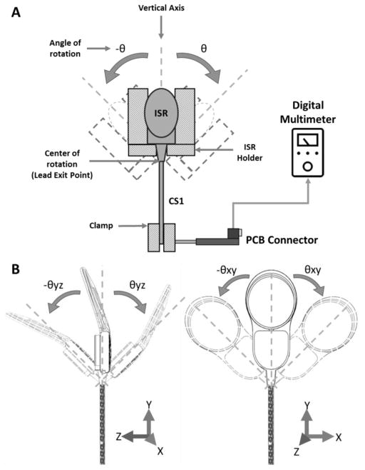
Figure 5.
Schematic of the ISR lead exit angular strain test setup. A) The setup consisted of a swinging fixture designed to hold the ISR at different orientations in order to produce the desired angle of deflection. The fixture was coupled to an oscillating machine that bent the ISR lead at the exit point. The ISR electrode lead exit point was placed at the center of rotation of the mechanism and the distal end of the lead was fixed with a clamp. B) Two different ISR orientations (0° and 90° about the Y-axis) at which the angular strain was applied as the distal end of the specimen was clamped.

