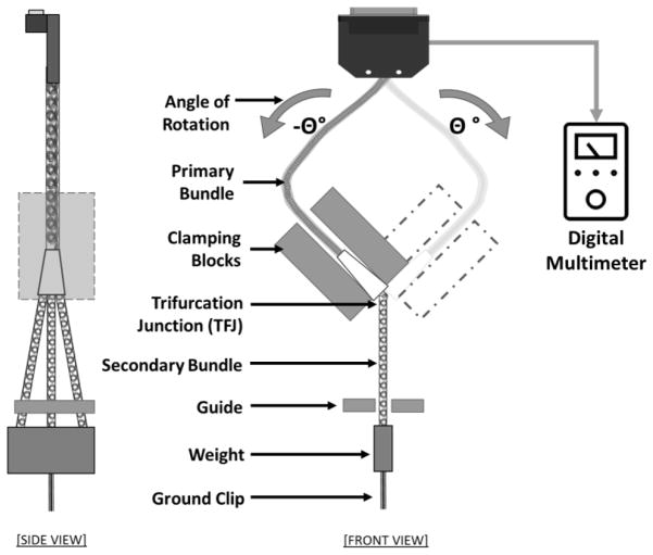
Figure 6.
Schematic of the trifurcation junction angular strain test setup. The TFJ was clamped to a rigid fixture with the three-secondary bundle exit points at the bottom edge. Each of the secondary bundles was passed through a guiding rail (non-contacting at rest position) and kept in slight tension by attaching an appropriate weight (about 3 grams) at the distal end of the three coil sheath tubes to keep the bundle straight. The holding fixture was coupled to an oscillating mechanism that flexed the TFJ at a rate of 2 Hz.

