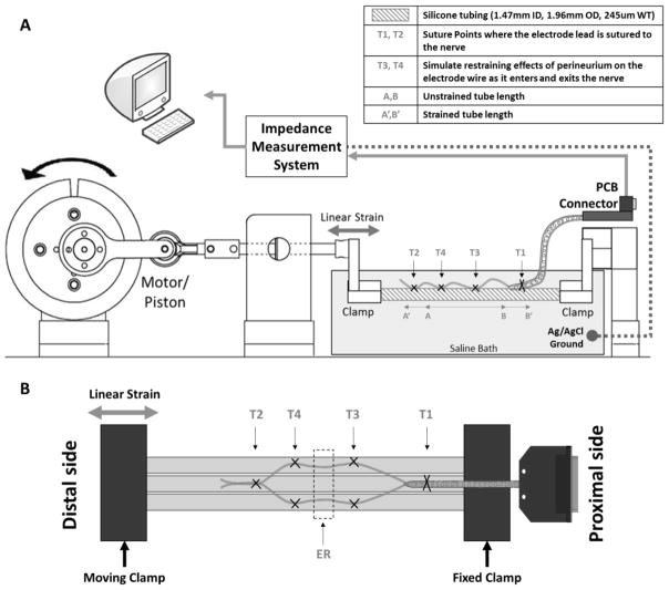
Figure 7.
Schematic of the secondary bundle exit point and nerve suture points linear strain test setup. A) The setup consisted of three small silicone tubes clamped together at one end (fixed clamp) and attached to a piston (moving clamp) at the other. The piston mechanism used a brushless motor coupled to a linear motion assembly to apply longitudinal cyclic strain to the tubes. B) A 3-tube configuration was employed in order to simulate implantation in multiple fascicles of a large diameter nerve. In this configuration, all five electrodes from an individual test specimen were attached to the tubes by anchoring the coil sheath to the middle tube with suture at point T1, then suturing (T3 and T4) the electrodes in groups of two and three to the outer tubes, with the exposed regions (ER) in between. These sutures simulate the restraining effect of the epineurium on each electrode wire as it entered and exited the nerve. Finally, all five electrode wires were anchored to the middle tube at suture point T2, and the tungsten needles were removed.

