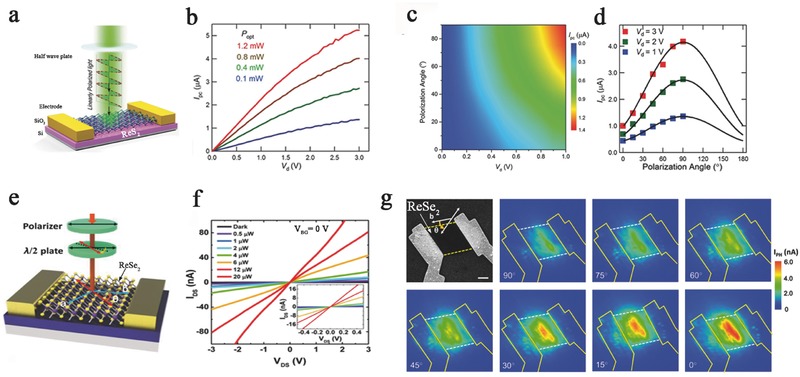
Figure 8.

a) The schematic of the ReS2‐based photodetection device under illuminating polarized light by the half wave plate. The photocurrent response as a function of drain voltage under b) different light intensity green light illumination, c) different polarization light illuminations, and d) different drain biases. Reproduced with permission.28 e) The schematic structure of ReSe2 photodetectors. The half‐wave plate was used to change the polarization direction. f) I ds–V ds of the photodetector with incident laser power varied from 0 to 20 µW. Inset: Small range of I ds–V ds with different incident laser powers. g) Scanning electron microscope (SEM) image of the polarization‐dependent photocurrent mapping of ReSe2 photodetector, showing prominent linear dichroic photodetection. Reproduced with permission.53 Copyright 2016, American Chemical Society.
