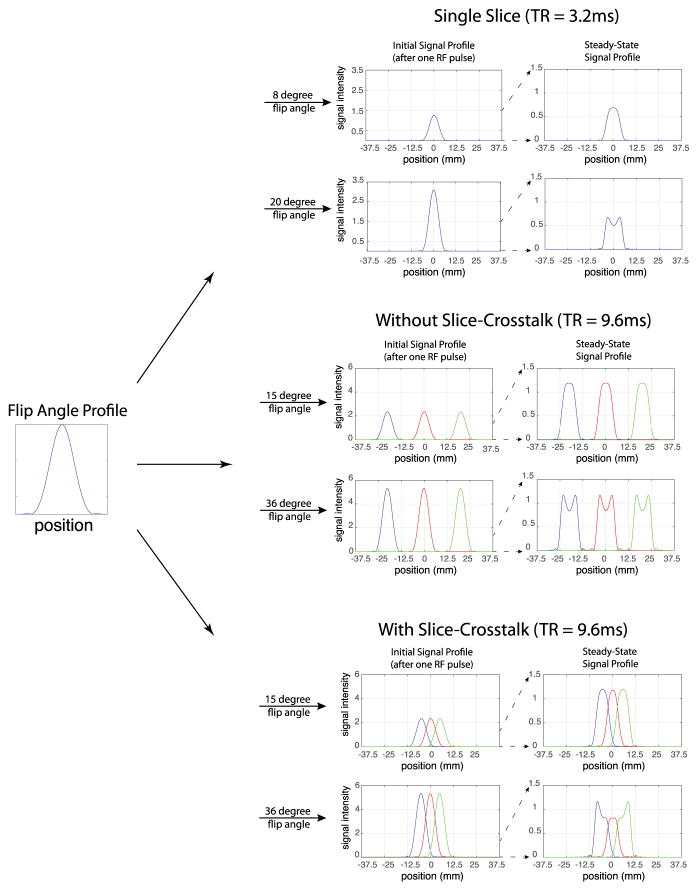
Figure 1.
Simulation of the slice initial signal profile and steady state signal profile for the RF pulse with slice excitation profile shown. Three different cases are demonstrated: the single slice acquisition case, a three slice multi-slice acquisition with large interslice gap (no slice crosstalk), and a three slice mutli-slice acquisition with zero interslice gap (showing slice crosstalk). The top row of each case uses a low flip angle that is close to the ideal maximum contrast flip angle (when an ideal slice excitation profile is assumed). The bottom row of each case utilizes a higher flip angle that is close to the actual maximum contrast flip angle.

