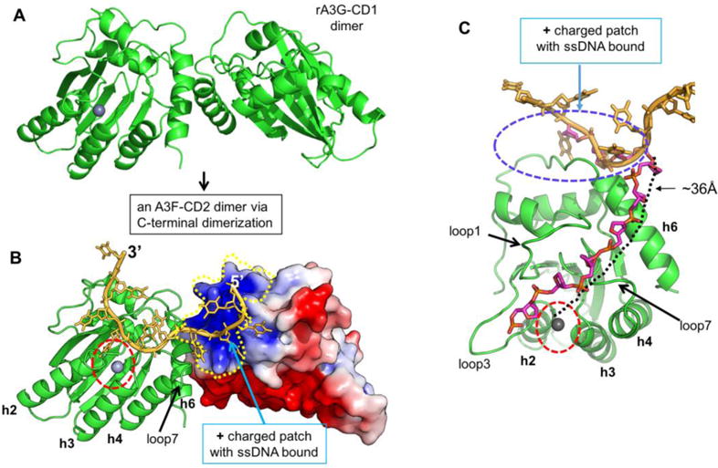
Figure 7.

Hypothetical model of A3F-CD2 binding to a ssDNA at the positively charged patch as a way of catching a substrate DNA. (A) The dimer structure of rA3G-CD1 (PDB ID 5K82) (32) that dimerizes through the C-terminal end around h6. (B) A dimer model of A3F-CD2 based on the rA3G-CD1 dimer interface, with one copy of A3F-CD2 drawn as a charged surface and the bound 10 nt poly-dT shown in orange. The Zn-active center (indicated by red circle) of one molecule of the dimer is next to the ssDNA that has one end bound to the positively charged surface of the neighboring A3F-CD2 molecule. (C) A model showing how the bound ssDNA (colored in orange) interacting with the A3F-CD2 positively charged patch located away from the active center can take a different direction (the ssDNA backbone colored in purple) to extend to the active center of the same A3F-CD2. The path is approximately 36 Å in length, which would require about six nucleotides of ssDNA (with a conformation of roughly 6.3 Å per nt). The active center Zn is indicated by a red circle.
