
Figure 1.
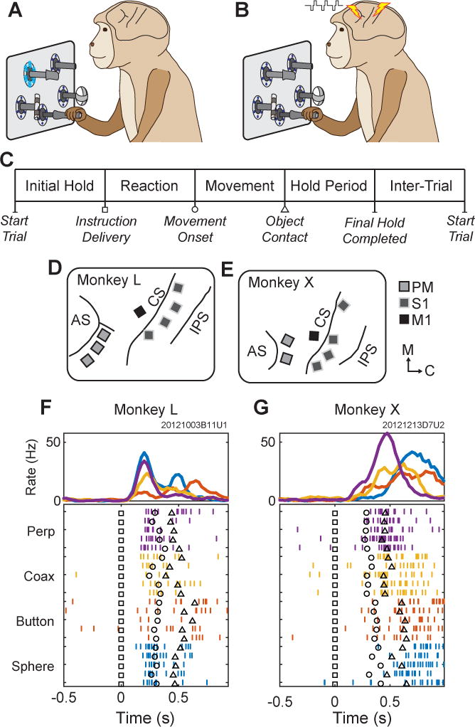
Task, instructions, and electrode locations. (A) Monkeys initially performed the reach-grasp-manipulate task instructed by blue LEDs. (B) Monkeys then learned to perform the same task instructed by ICMS delivered in either PM or S1. (C) Sequence of task epochs. (D,E) Floating microelectrode array locations in (D) monkey L and (E) monkey X. Light gray squares with dark outlines represent arrays in PM; dark gray squares with light outlines, S1, and black squares, M1. AS-arcuate sulcus, CS-central sulcus, IPS-intraparietal sulcus. Orientation arrows: M–medial, C–caudal. (F,G) Typical unit activity recorded from a PM electrode in each monkey during RGM movements (LED Instructions) involving each object: perpendicular cylinder (Perp, purple); coaxial cylinder (Coax, yellow); button (red); and sphere (blue). Only five trials of each movement are shown in the raster display, whereas ~20 trials of each are averaged in the histograms. Trials have been aligned at the instruction onset (Time=0, black squares in the raster trials). Additional markers indicate the time of movement onset (black circle) and target object contact (black triangle) in each trial.