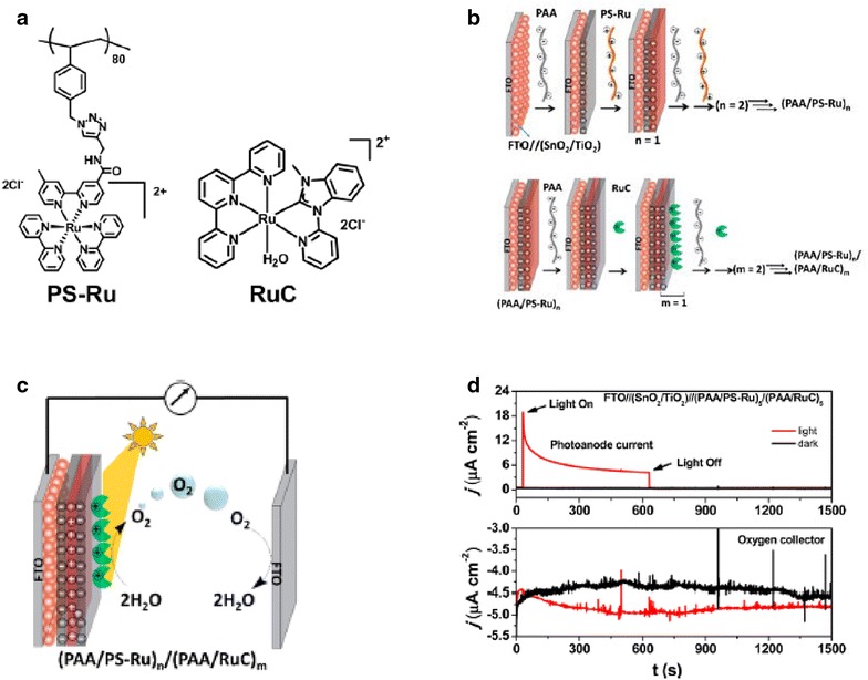
Fig. 6.

a Structures of polychromophore (PS-Ru) and catalyst (RuC). b Schematic of the step-wise assembly of the LbL interface using a mesoporous SnO2/TiO2 core/shell layer deposited on a fluorine doped tin oxide (FTO) substrate. c Scheme depicting the C–G setup for detecting photochemically generated O2 by the (PAA/PS-Ru)n/(PAA/RuC)m prepared electrodes. d Current–time traces for the as prepared photoanode under bias with the simultaneous current response measured at the FTO collector electrode shown below
(Reproduced with permission from Ref. [26]. Copyright 2016, American Chemical Society)
