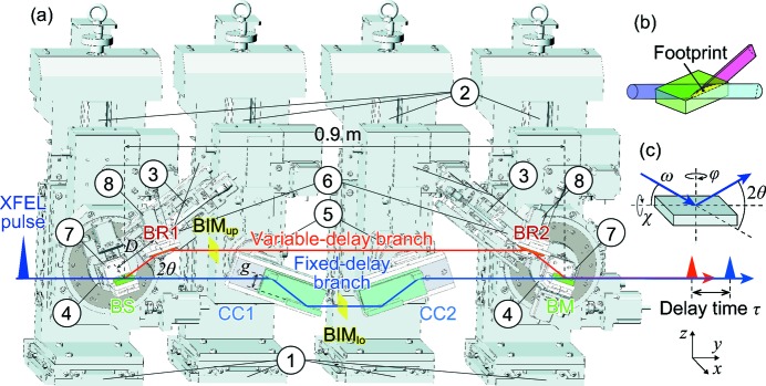
Figure 1.
(a) Illustration of the mechanics of the SDO system. Crystals BS, BRs, BM and CCs represent the beam splitter, beam reflectors, beam merger and channel-cut crystals, respectively. Translation stages in the (1) x, (2) z and (3) D directions. Rotation stages around the (4) ω–2θ axis for BS/BM, (5) ω axis for CCs and (6) ω axis for BRs. Swivel stages around the χ axis for (7) BS/BM and (8) BRs. The range of D is set to 57–127 mm. Beam intensity monitors (BIMup and BIMlo) are inserted into the two delay branches. Conceptual sketches of (b) wavefront division and (c) four general axes in X-ray diffraction.

