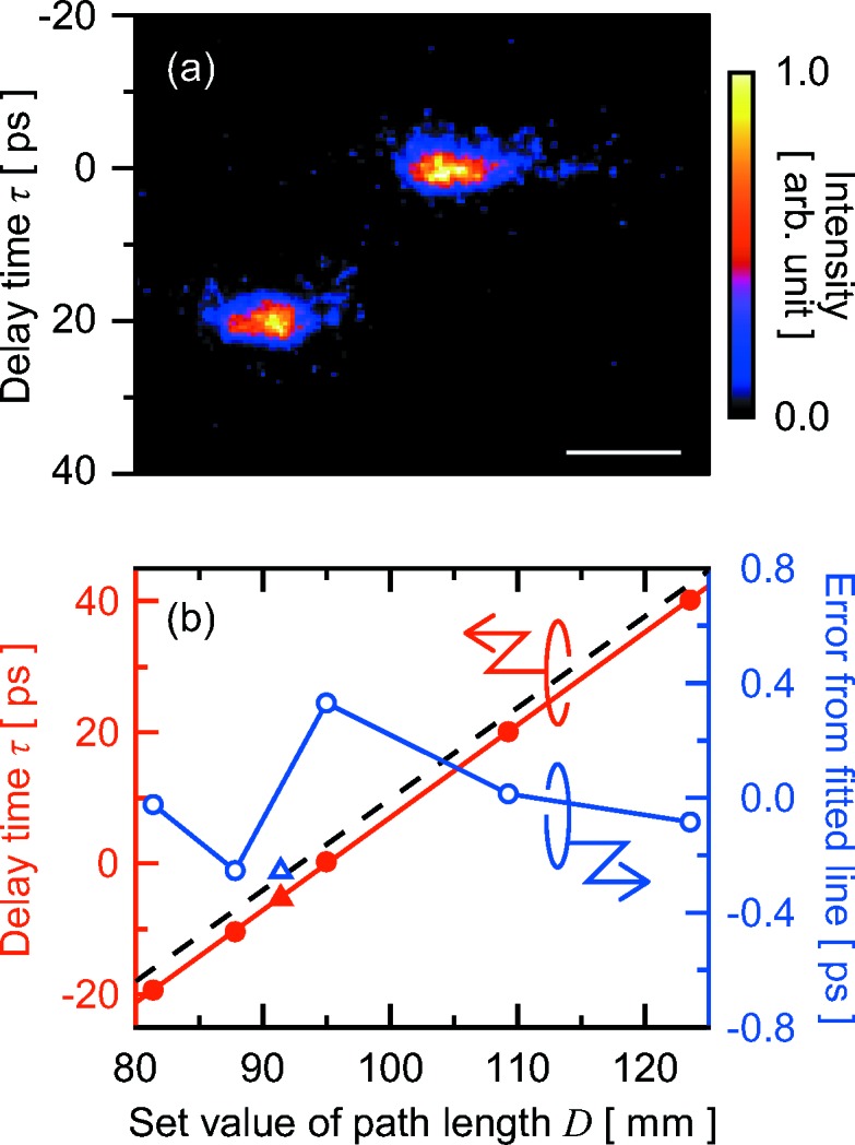
Figure 5.

(a) Typical split-and-delayed pulses measured with the X-ray streak camera. The delay time between two pulses was set to be 20 ps. Profiles in the horizontal and vertical directions correspond to spatial (horizontal) and temporal information, respectively. The width of the temporal distribution of each pulse, ∼3 ps, was due to the effective resolution of the camera. The scale bar represents a length of 0.4 mm. (b) Delay time as a function of the setting path length between adjacent BS/BM and BRs. Averaged delay times at each set value of the path length are displayed as closed red circles. The solid red line represents the fitted line. Open blue circles indicate the errors from the fitted line. The dashed black line represents the calculated line in the ideal condition. Closed red and open blue triangles indicate averaged delay time and the error from the fitted line, respectively, measured after the delay scan plotted as circles.
