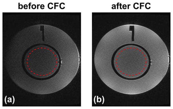
FIG. 9.
The ACR phantom images acquired using a 3D T2 FLAIR sequence before (a) and after (b) the zeroth/first-order CFC, and reformatted into the axial plane. Red circles indicate the ROIs used in the SNR measurement provided in Table 1. The ringing at the patient’s left end of the phantom is suspected to be free induction decay artifacts.

