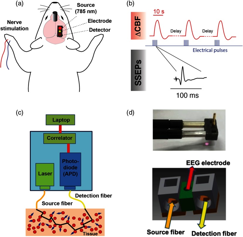
Fig. 1.
Experimental design and measurement apparatus. (a) Schematic of the recording and stimulation configuration. A DCS probe tip containing optical fibers is placed on the region of the skull above the primary somatosensory cortex, at a location coinciding with the forepaw’s representation. A recording EEG electrode is inserted through the center of the probe. Pulses of electrical current are delivered to the contralateral limb with respect to the optical and electrophysiological measurements. Closed-skull impact is delivered by a 5-mm impactor tip anterior and lateral of bregma contralateral to the optical measurement (see Sec. 2). (b) Overview of synchronization between stimulus, measurements of CBF, and SSEPs. The red traces depict simulated hemodynamic signals, which are broad compared with electrophysiological potentials (note the time scale difference in the insets). The blue pulses indicate electrical stimuli delivered to the median nerve. (c) Block diagram of the DCS device used in this study. (d) Photograph and schematic of the 3-D-printed DCS probe tip. Light is delivered and collected from the tissue through fiber optics that are coupled to the skin with microprisms.

