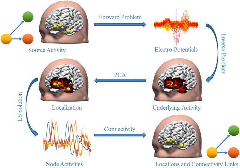
Figure 1. An overview of the simulation procedures.
After EEG electrodes and iEEG electrodes are placed within a realistic head geometry, the location of the network nodes is randomly selected and a connectivity link is created among these nodes based on MVAR models (here node 1 is driving nodes 2 and 3). Then the forward problem is solved to calculate the potentials at the electrodes and noise (AWGN and ACGN) is added to these simulated potentials. The inverse problem is then solved and PCA is performed on the estimated source activities to determine the location of the simulated network nodes. Consequently, the activity of these nodes over time is extracted. These activities are then used to detect the connectivity links among the mentioned nodes.

