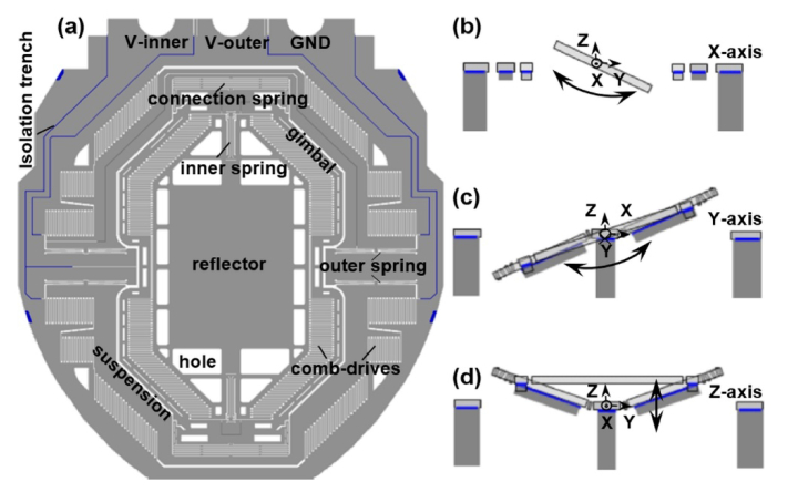
Fig. 4.
a) Reflector with dimensions of 1800 and 1200 µm2 is attached to a gimbal frame driven laterally by actuators coupled to b) inner (X-axis) and c) outer (Y-axis) torsional springs. d) U-shaped suspensions displace the reflector out-of-plane in the Z-axis. Isolation trenches are etched in the device layer to electrically isolate the drive signals between the inner and outer comb-drives.

