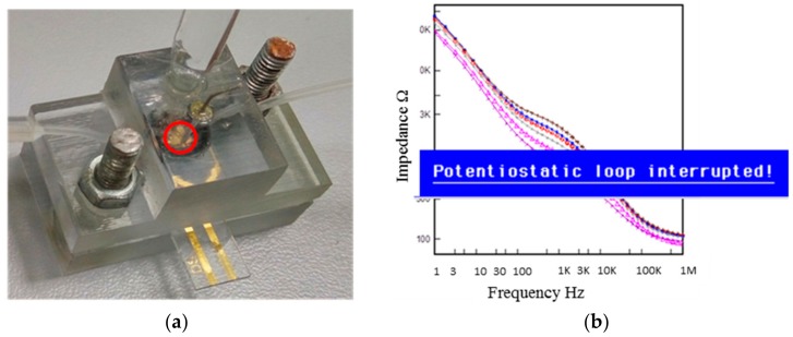
Figure 1.
(a) Assembled microfluidic device with reference, counter and working electrodes. The bottom and top parts of the device were mounted via bolts and the working area was fixed using an o-ring. The inlet and outlet tubes were positioned at 45° from the sensing surface. The inlet tube was connected to the pumping system, which permitted the liquid flow at a specified flow rate. The red circle encloses the area where air bubbles formed during the course of the experiment. (b) Error message obtained during impedance measurement: “Potentiostatic loop interrupted.” In the background, typical data for impedance vs. frequency measurement after protein binding.

