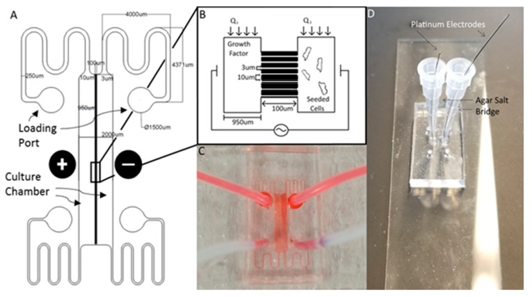
Figure 1.
The Gal-MµS. (A) Schematic of the design illustrating channel arrays separating two culture chambers. Electrodes are placed on either side of the culture chambers to facilitate controlled application of electric fields. (B) Cartoon schematic illustrating Gal-MµS operation, not to scale. Cells are loaded into one culture chamber, while the desired chemical stimulant is loaded into the other. Establishing the flow ratio, Q1:Q2, provides control of the chemical concentration gradient experienced by cells within the culture chambers. The electrodes positioned on either side of the two culture chambers to enable controlled concurrent electrical stimulation. (C) Image of the device (without electrodes) showing fluid flow within culture chambers. (D) Image of device demonstrating electrode placement and composition.

