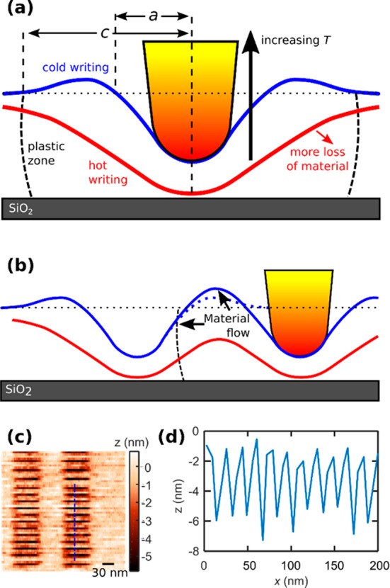
Figure 6.

(a) Schematics of the patterning process. Blue and red lines indicate estimated profiles for cold and hot (above the decomposition temperature) patterning, respectively. The profiles patterned at cold conditions are less deep because of enhanced elastic recovery. In addition, we expect that material is pushed backward along the line, partially refilling the previously patterned pixel. For hotter patterning, the yield stress is reduced and material is partially or fully removed. This leads to deeper lines at lower force. However, the temperature gradient in the tip and the stack reduces the steepness of the profile. (b) For cold patterned lines (blue line), the material flow in the plastic zone first increases the rim height (the dotted line indicates the undisturbed profile) and at closer pitch reduces the line depth. As long as plastic deformation is present, the plastic zone will have a similar extent, limiting the proximity of the neighboring lines. For hot patterning (red line), plastic deformation can be absent, but the widening of the profile restricts resolution. (c) Topography image of a 9 nm half-pitch pattern in a 5 nm thick PPA layer on 20 nm polymethylglutarimide. (d) Cross section along the blue line in (c), indicating 4 nm pattern amplitude.
