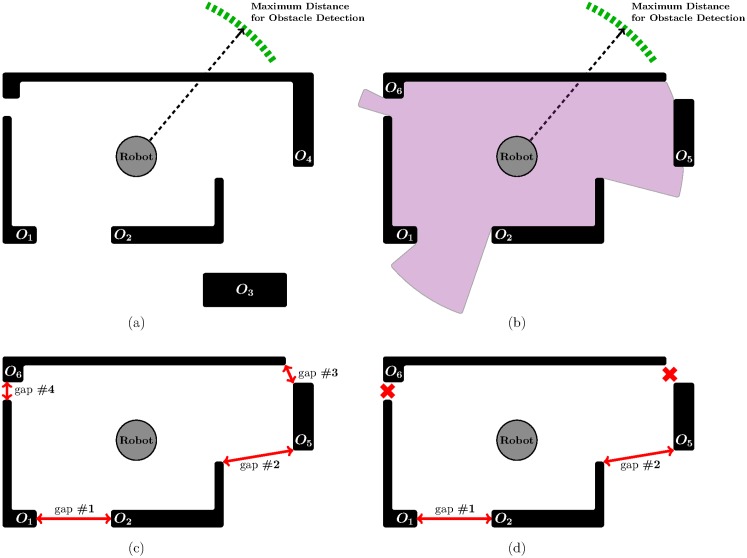
Fig 1. TGF in action: An example showing the execution of stage S1.
(a) the environment where the robot should navigate (obstacles are represented by the thick black lines as well as the black rectangle; the robot is assumed to be equipped with a laser scanner which measures the distance to all surrounding obstacles in a 360-degree field of view); (b) the environment as locally perceived by the robot; (c) detection of gaps between obstacles; (d) gaps #3 and #4 are eliminated, because these gaps are narrower than the robot.

