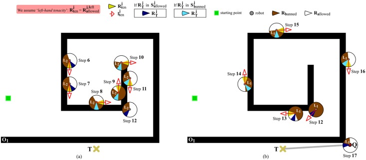
Fig 12. Continuation of the navigation task initiated in Fig 11(a) and 11(b).
The situation depicted makes clear that EG allows the robot to progress directly towards the target point (meanwhile, the robot persists in performing boundary-following) just when the robot reaches the outermost loop of the spiral-like obstacle and the currently-active layer of the short-term memory indicates that there is a free-obstacle path to T. (a) At step 12, layer #2 is destroyed, and layer #1 is recovered and used for deciding where to move the robot. (b) At step 17, the robot leaves the O1’s boundary and moves following the thick gray line. In both figures, (a) and (b), Li stands for layer #i. Lastly, it is also important to note that the legend of this figure gives a different meaning to some colors as compared to the legend of Fig 11(a) and 11(b). Essentially, now the angular region is painted in either dark-blue or soft-blue depending on how it is labelled: dark-blue/soft-blue is used when is labelled as allowed/banned.

