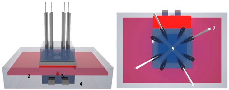
Figure 1.
Schematic design of the four-chamber heat-transfer method (HTM) setup: (Left panel) overview: the sensor chip (1) was placed on a copper lid (2), which was used as a heat sink. The central cavity in the copper lid is intended to install a thermocouple (3). The assembly is heated by power resistor (4). (Right panel) top view: the sensor was divided into four triangular shaped identical sections of 10 mm2 (5) with a height of 1 mm by means of a polydimethylsiloxane (PDMS) flow cell. Each flow cell connects to two Teflon tubes serving as fluid in- and outlet (6) and thermocouple holders (7), respectively. An alternative 2D representation of the setup can be found in [22].

