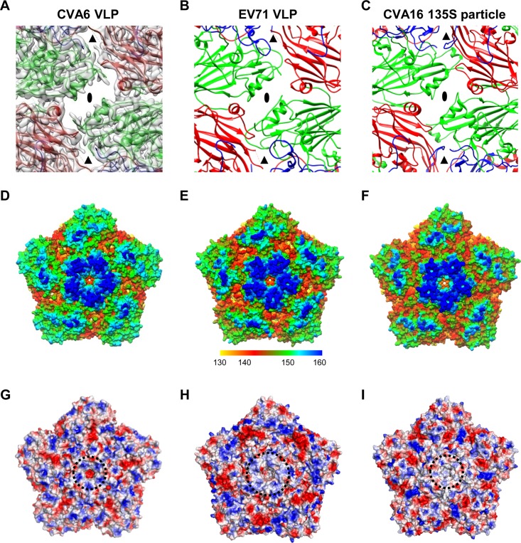
FIG 3.
Surface features of the CVA6 VLP compared to those of the EV71 VLP and CVA16 135S particle. (A) A map and model overlay viewed along the 2-fold symmetry axis (marked as a black ellipse) for the CVA6 VLP. The position of the junction channel is indicated by a black triangle. The density map is shown in transparent gray. (B and C) Atomic models of the outer surfaces of the EV71 VLP (PDB 4YVS) (B) and the CVA16 135S particle (PDB 4JGY) (C) viewed in the same direction as in panel A. (D to F) Surface representation of the pentameric structures of the CVA6 VLP (D), EV71 VLP (E), and CVA16 135S particle (F) viewed along the 5-fold symmetry axis. The surface is radially colored. The color bar labels the corresponding radius from the center of the particle (in angstroms). (G to I) Electrostatic surfaces of pentamers of the CVA6 VLP (G), EV71 VLP (H), and CVA16 135S particle (I). The electrostatic potential was calculated by utilizing PyMOL; the positively and negatively charged areas are shown in blue and red, respectively. The black dashed circle indicates the 5-fold positively charged patch.

