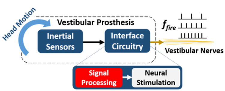
Fig. 1.

Vestibular Prosthesis (VP) block diagram. A VP mimics the operation of peripheral vestibular organs by encoding head motion into firing rate, ffire, at the vestibular nerves by means of inertial sensors and an interface circuitry. The circuitry consists of signal processing and neural stimulation blocks. Signal Processing implemented as an ASIC is reported here.
