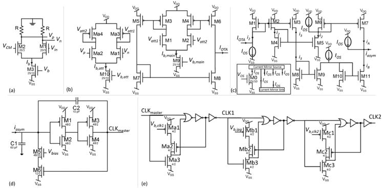
Fig. 7.

Frequency encoding blocks. (a) Variable gain amplifier. (b) Variable-gain OTA. (c) Asymmetric current mirror. The inset shows the circuit generating the offset current, IOS. (d) Current-controlled oscillator. (e) Clock generation. Three glitch circuitry are cascaded to generate two clocks (CLK1 and CLK2) that are out of phase by an interphase gap amount.
