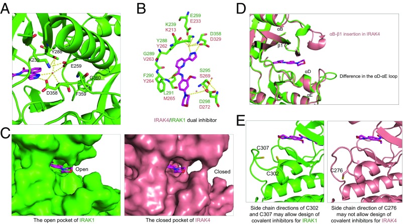
Fig. 4.
Detailed mode of inhibitor interaction. (A) A hydrogen-bonding network around the IRAK1 gatekeeper residue Y288 near the head of the inhibitor. (B) Interactions of IRAK1 with JH-I-25. IRAK1 residues are labeled in green while the corresponding IRAK4 residues are shown in pink. (C) Surface diagrams of IRAK1 (Left, green) and IRAK4 (Right, pink) at the tail of the inhibitor pocket, showing the openness of IRAK1 and closeness of IRAK4. (D) Superimposed IRAK1 and IRAK4 at the region of the ATP front pocket showing that an insertion in IRAK4 and distinct loop conformations are responsible for the difference in the openness of this region. (E) Side chain directions of C302 and C307 in IRAK1 may allow design of covalent inhibitors, but the side chain direction of C276 of IRAK4 may not.

